Background
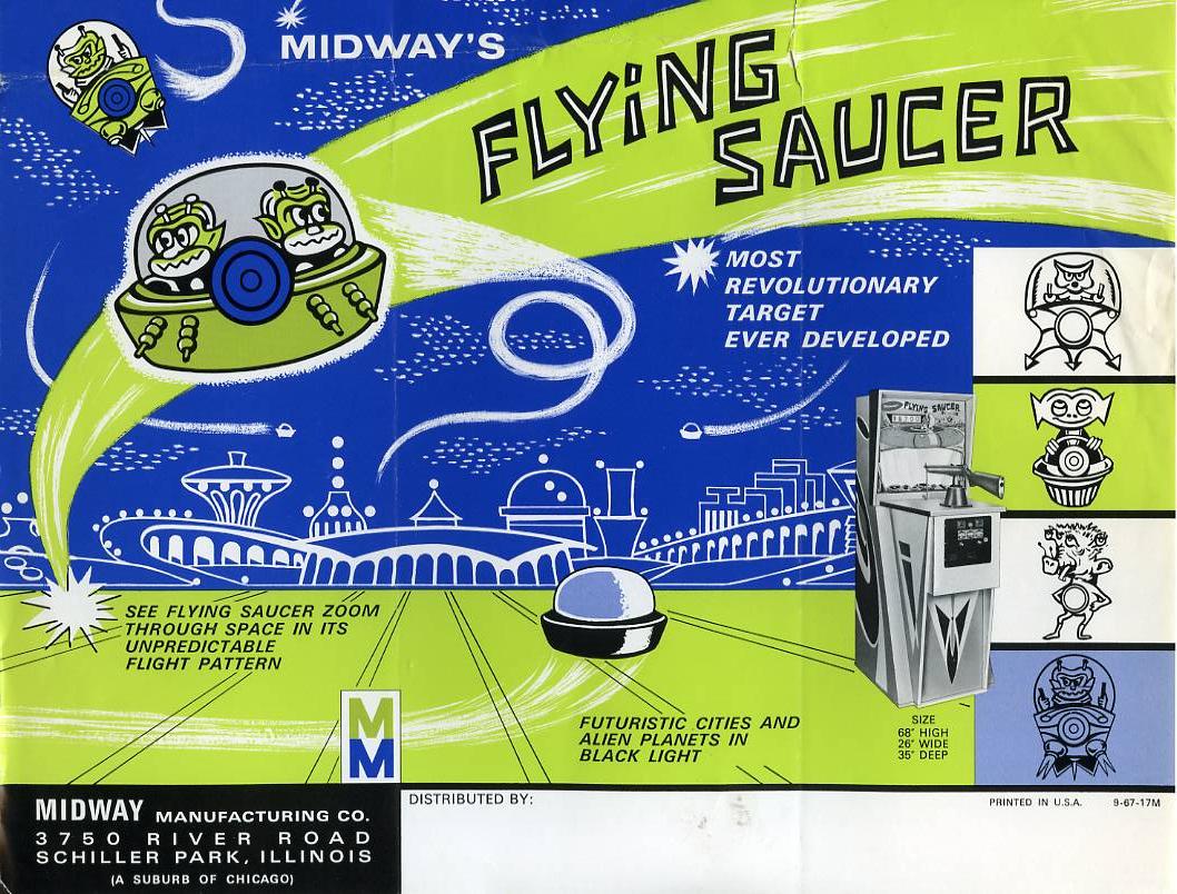
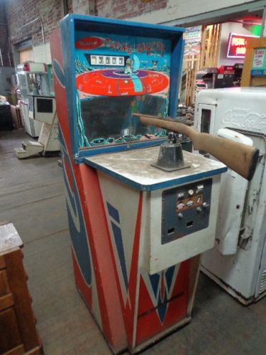
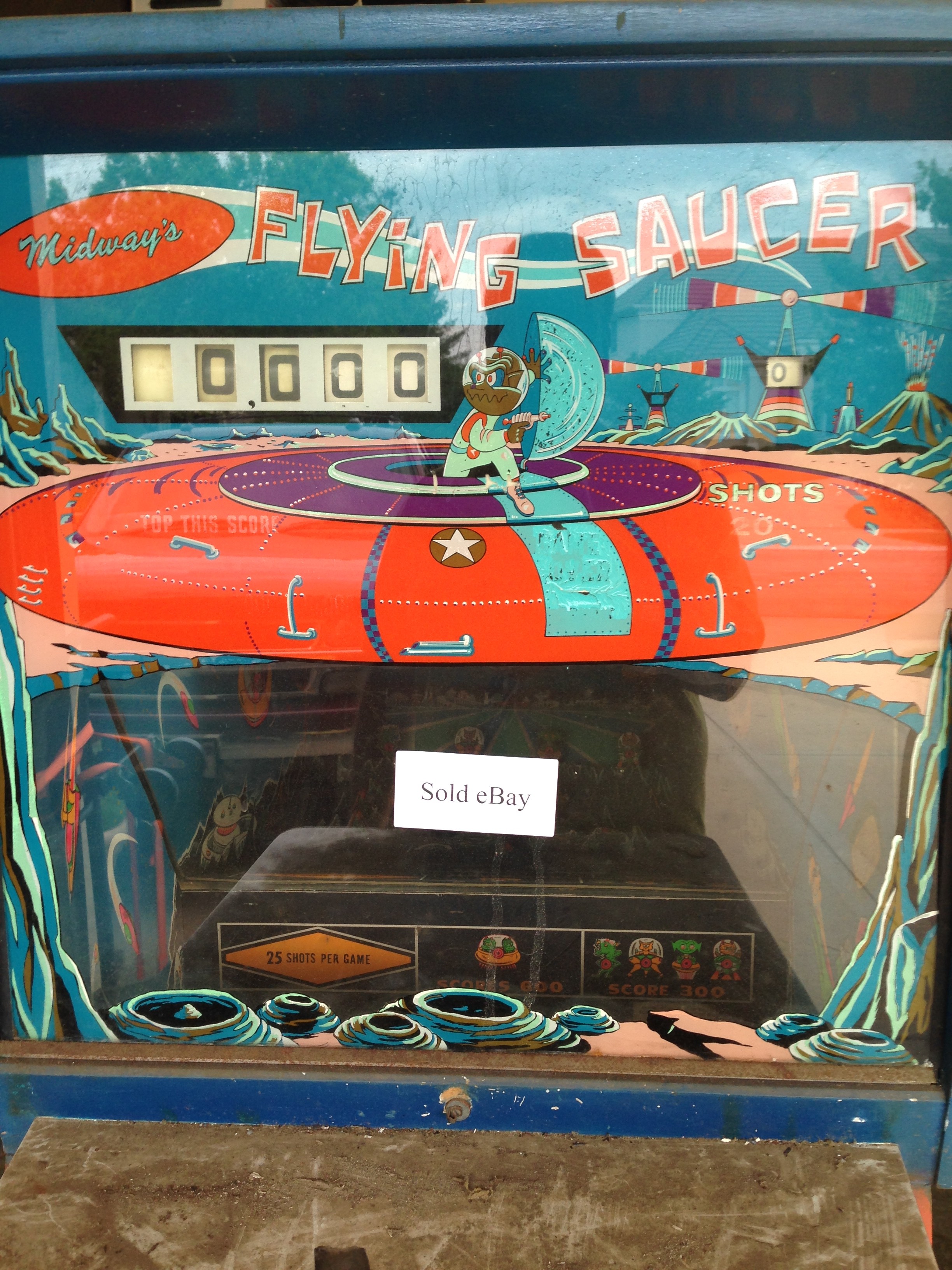
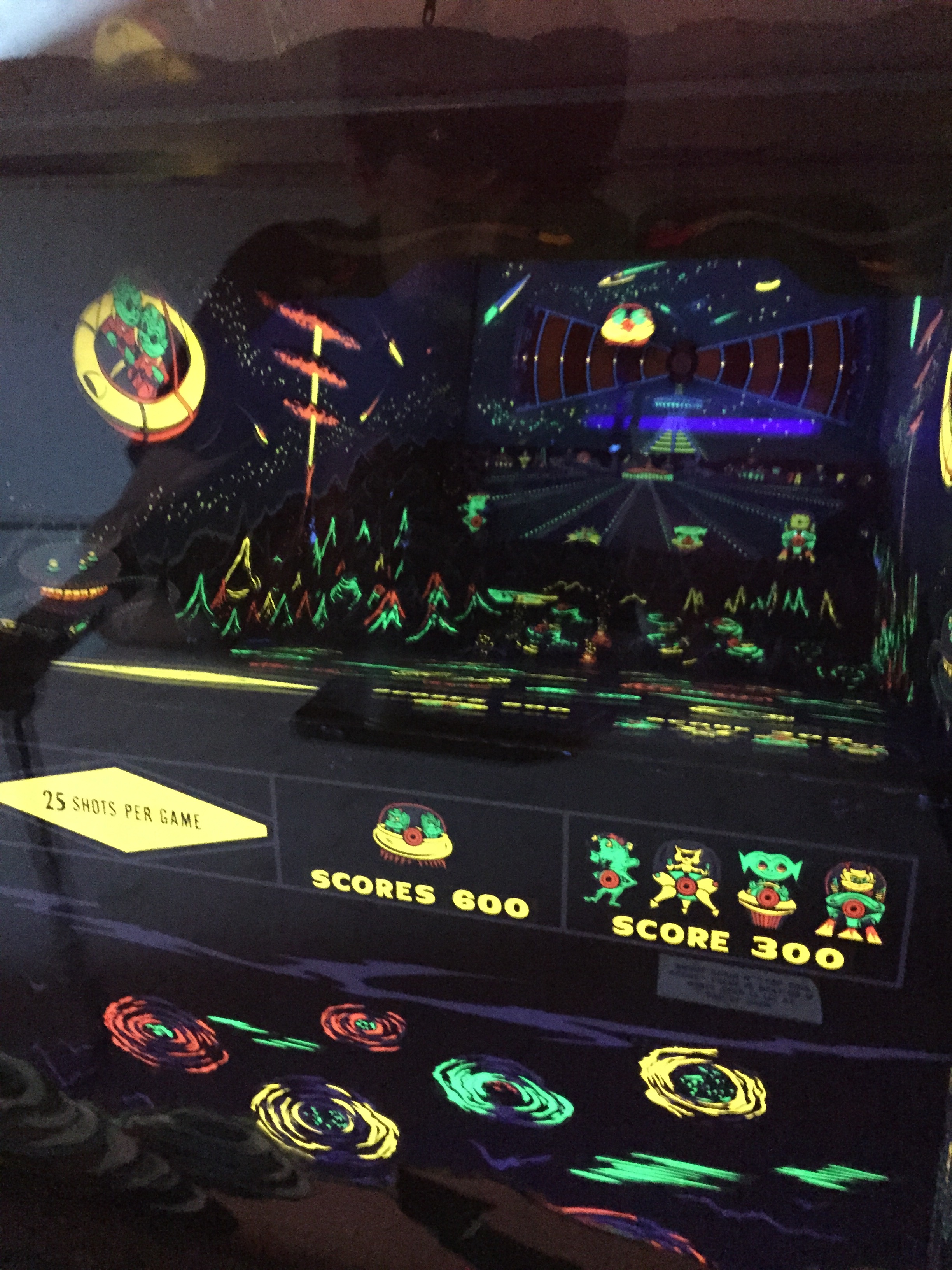
I finally found a gun game project. This one is a Midway Flying Saucer.
Wikipedia has a good article about the history of Midway Manufacturing. There is an interesting reference to work that Bally (early owner of Midway) had been doing on a home games console and a possible entry into the home computer market.
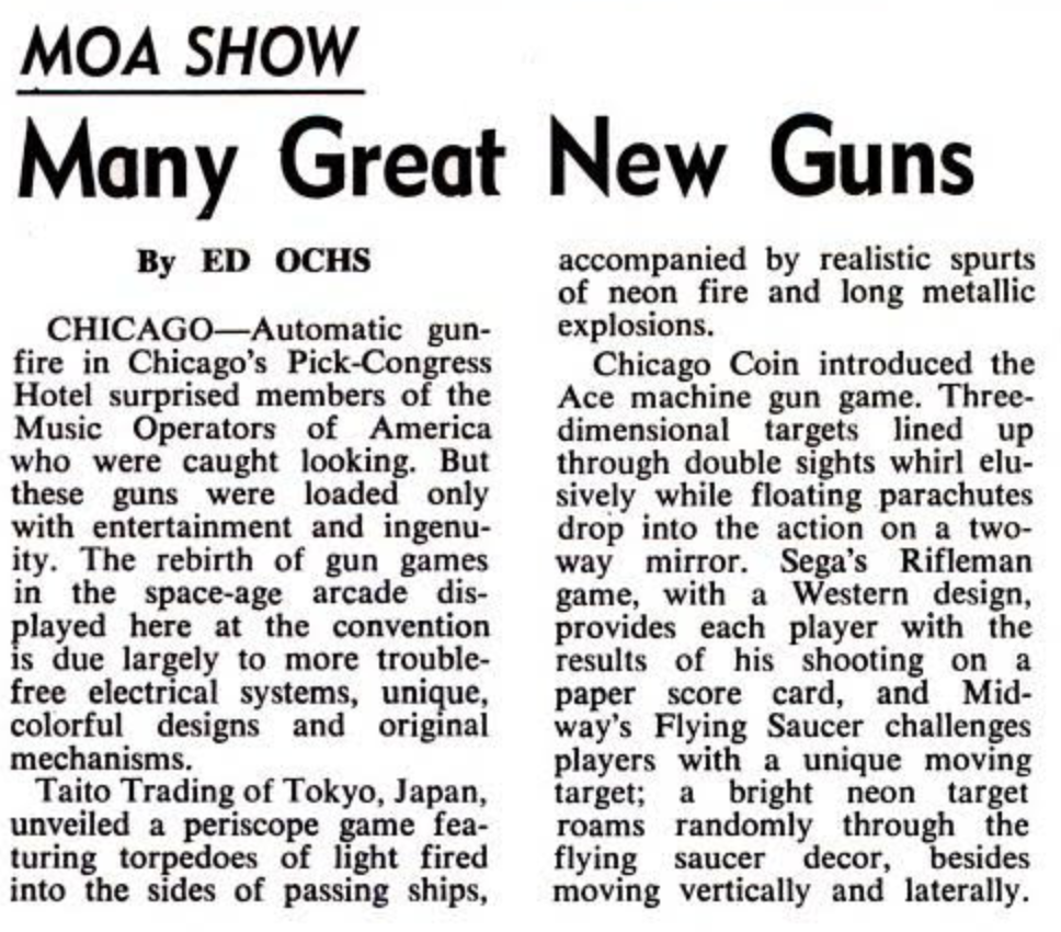
Article from a 1968 Billboard magazine about the “Music Operators of America” show where new gun games, including Flying Saucer, were featured.
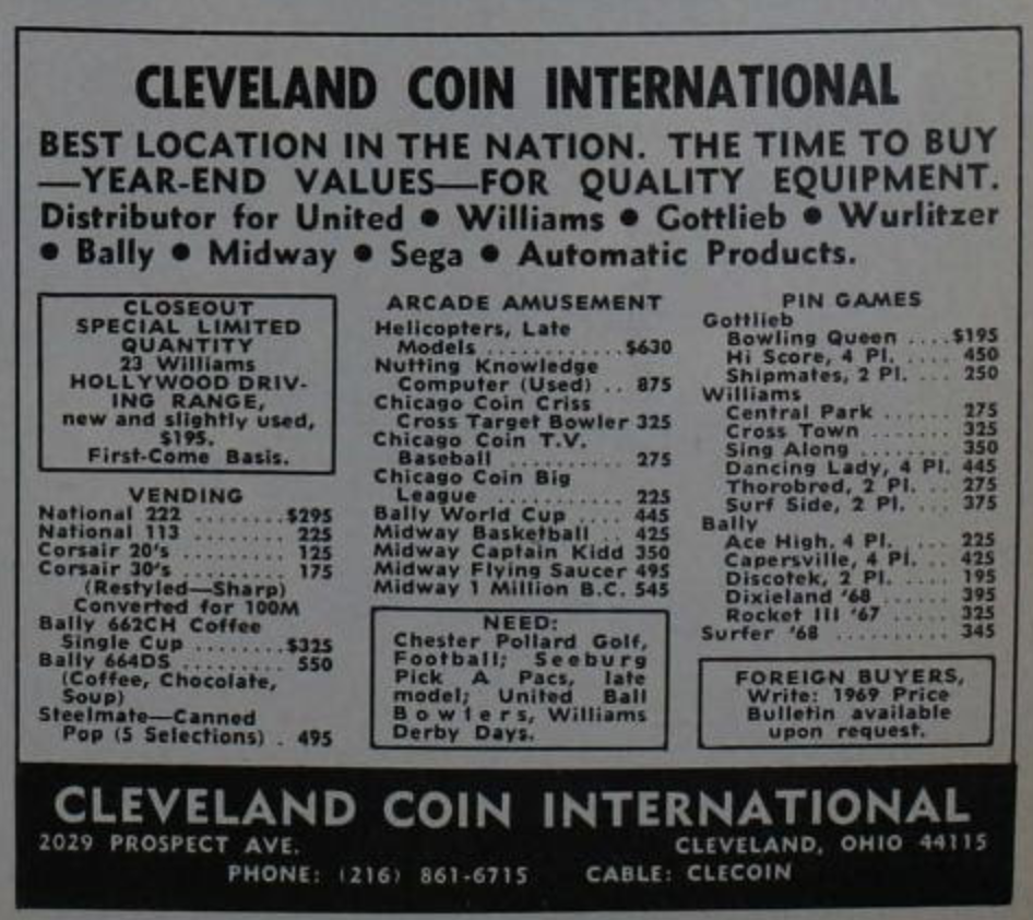
Appearently they were selling for $495 in 1968
Reference Information
I haven’t been able to find a manual or parts list for this game, but here are links for a similar machine called Twin Pirates. Marco does offer a schematic thankfully. The 1970 Midway parts catalog does list some parts for this game, but does not reference the game specifically. I’m guessing it must be in the previous Midway Parts Catalog, but I have haven’t been able to find one yet.
Twin Pirates Parts Manual
Twin Pirates Manual

Flying Saucer Schematic
(I had to scan this with a handheld wand scanner, and stitch the two scans together. This is the first time I’ve done this, so hopefully it came out ok).
Here’s some additional information from the 1970 Midway Parts Catalog, from a game called Flying Carpet, which appears almost mechanically identical.
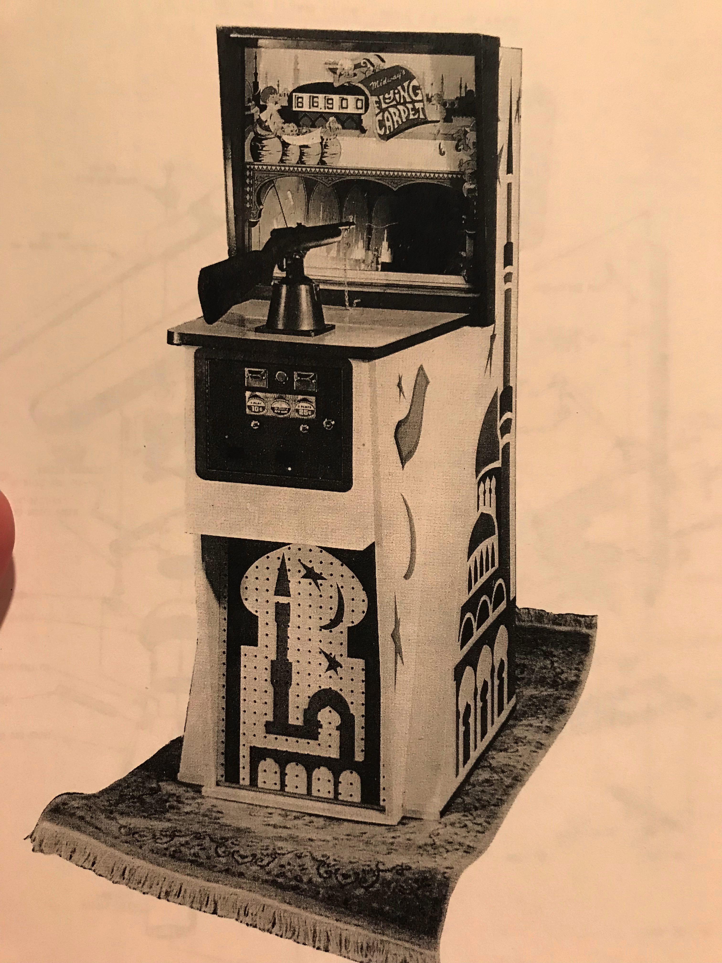
Midway Flying Carpet Gun Game
These are fairly hi-res images and you should be able to zoom-in to see part numbers etc.
John’s Jukes still has some NOS parts for these old Midway Machines.
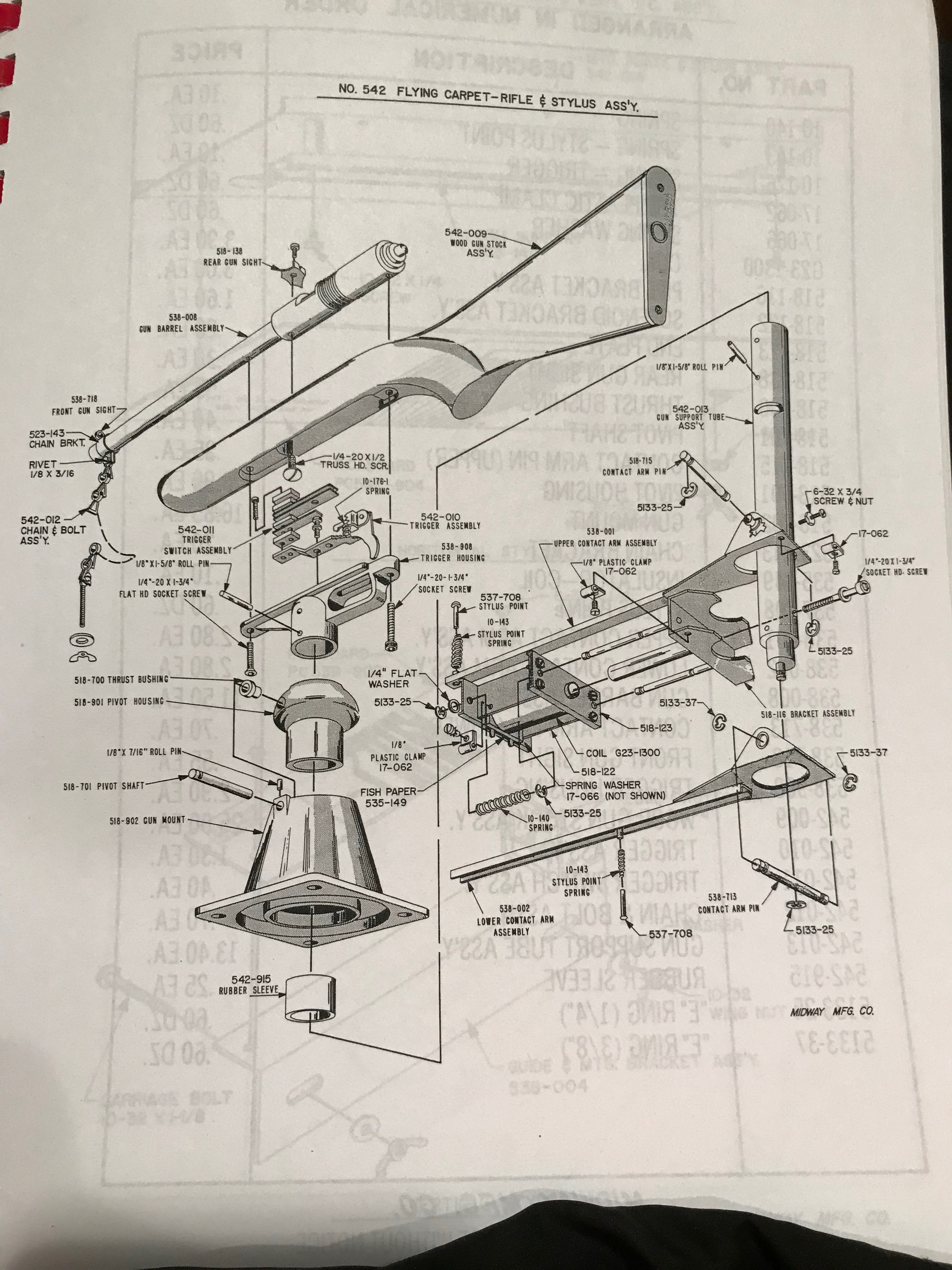
Gun Assembly
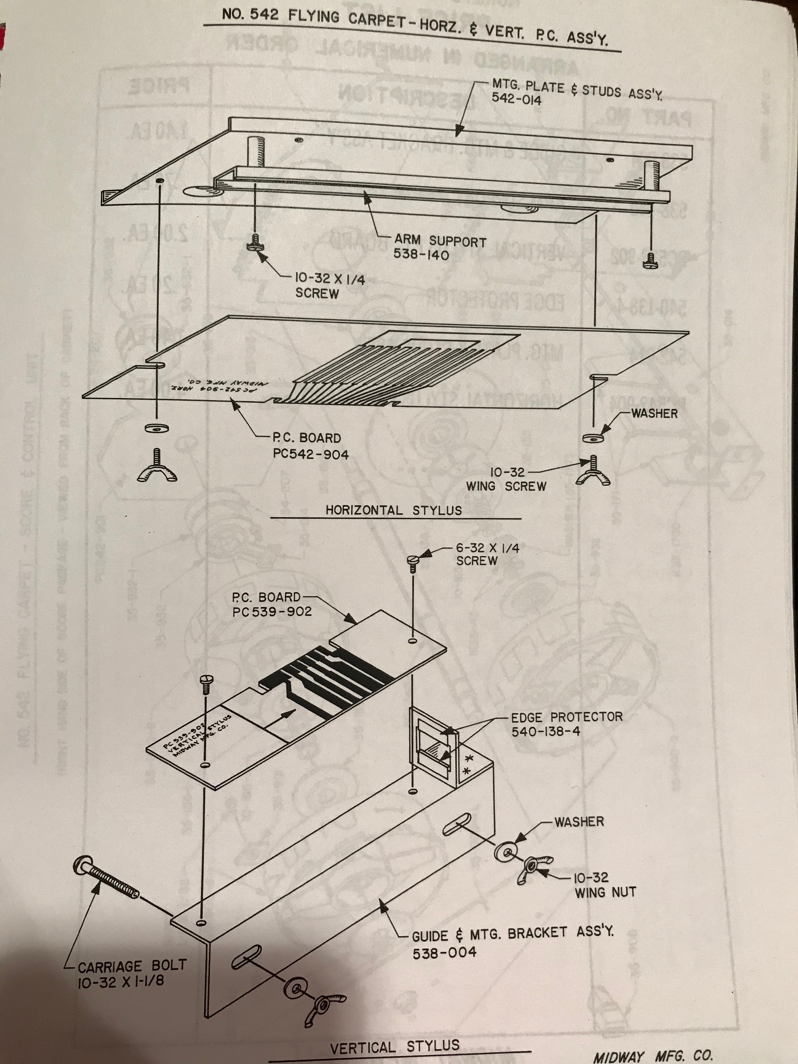
Vertical and Horizontal Gun Wipers
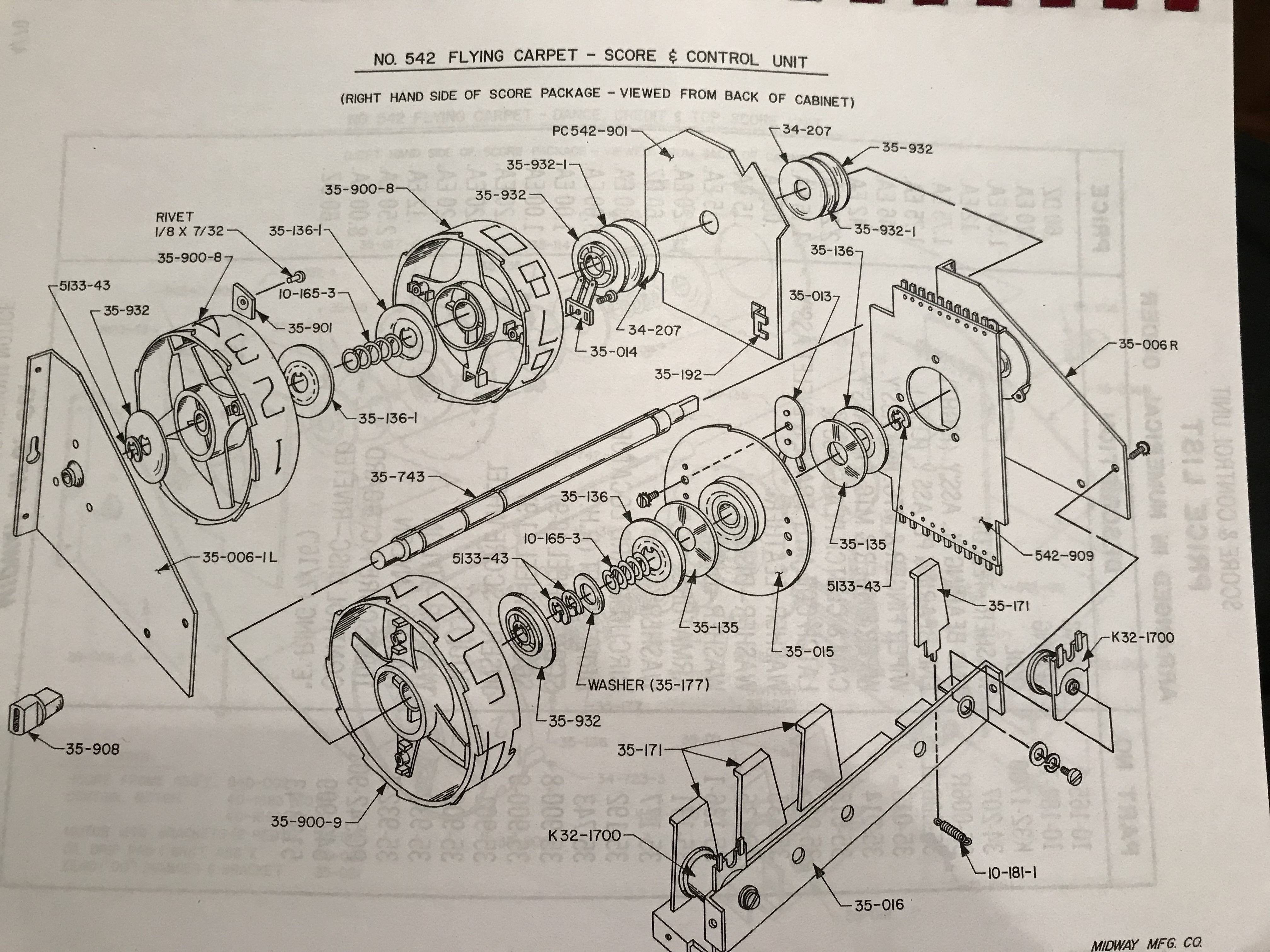
Score Unit Assembly
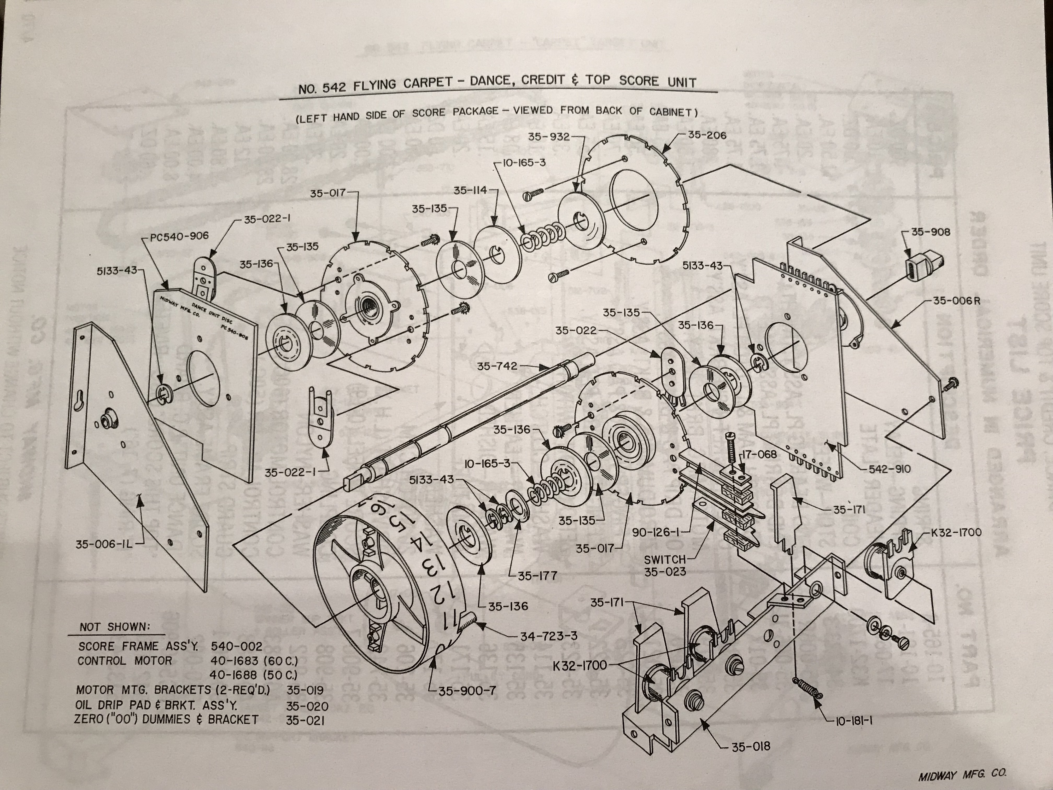
Dance, Top Score, and Credit Units Assembly
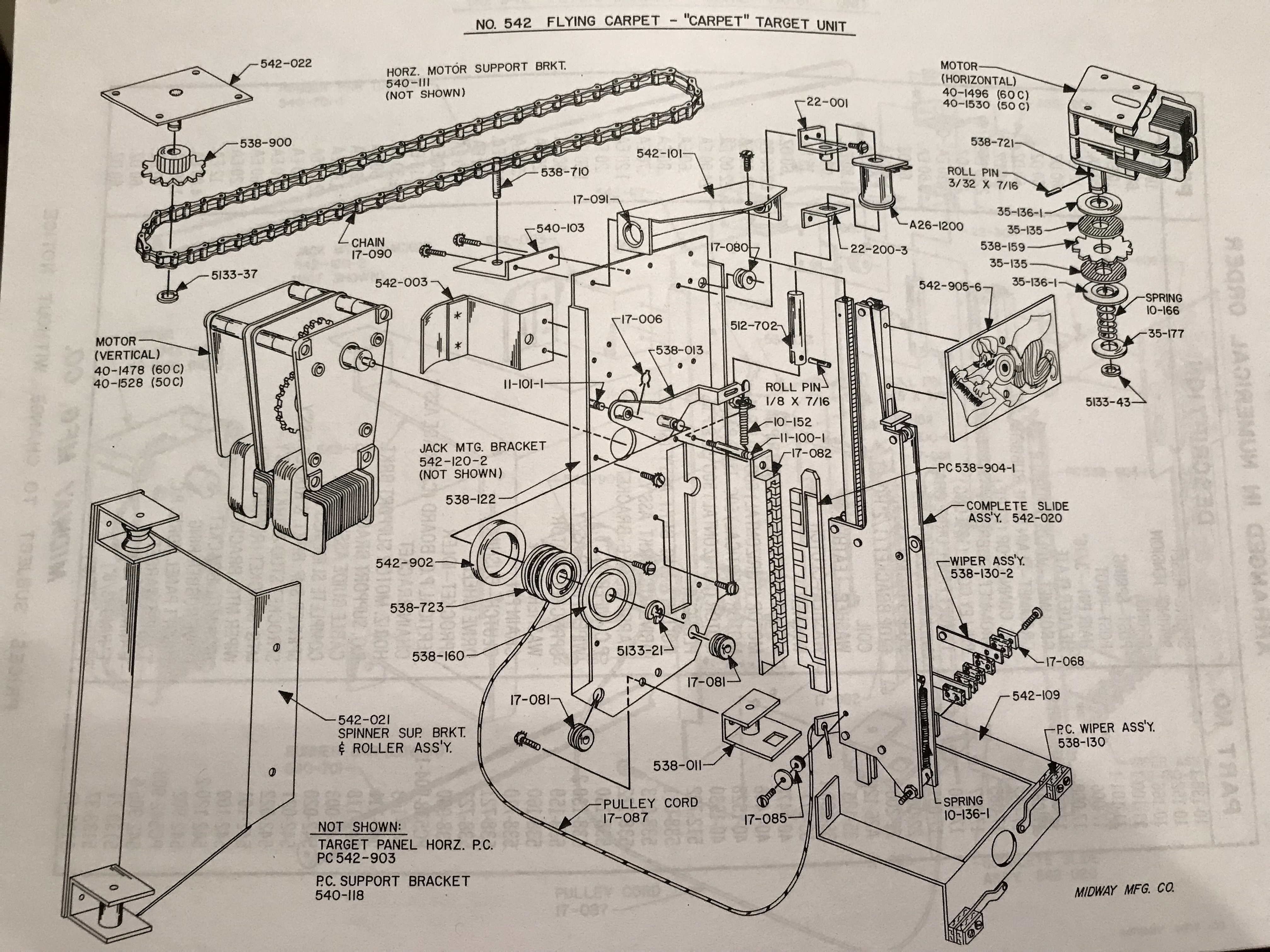
Dancing Target Assembly
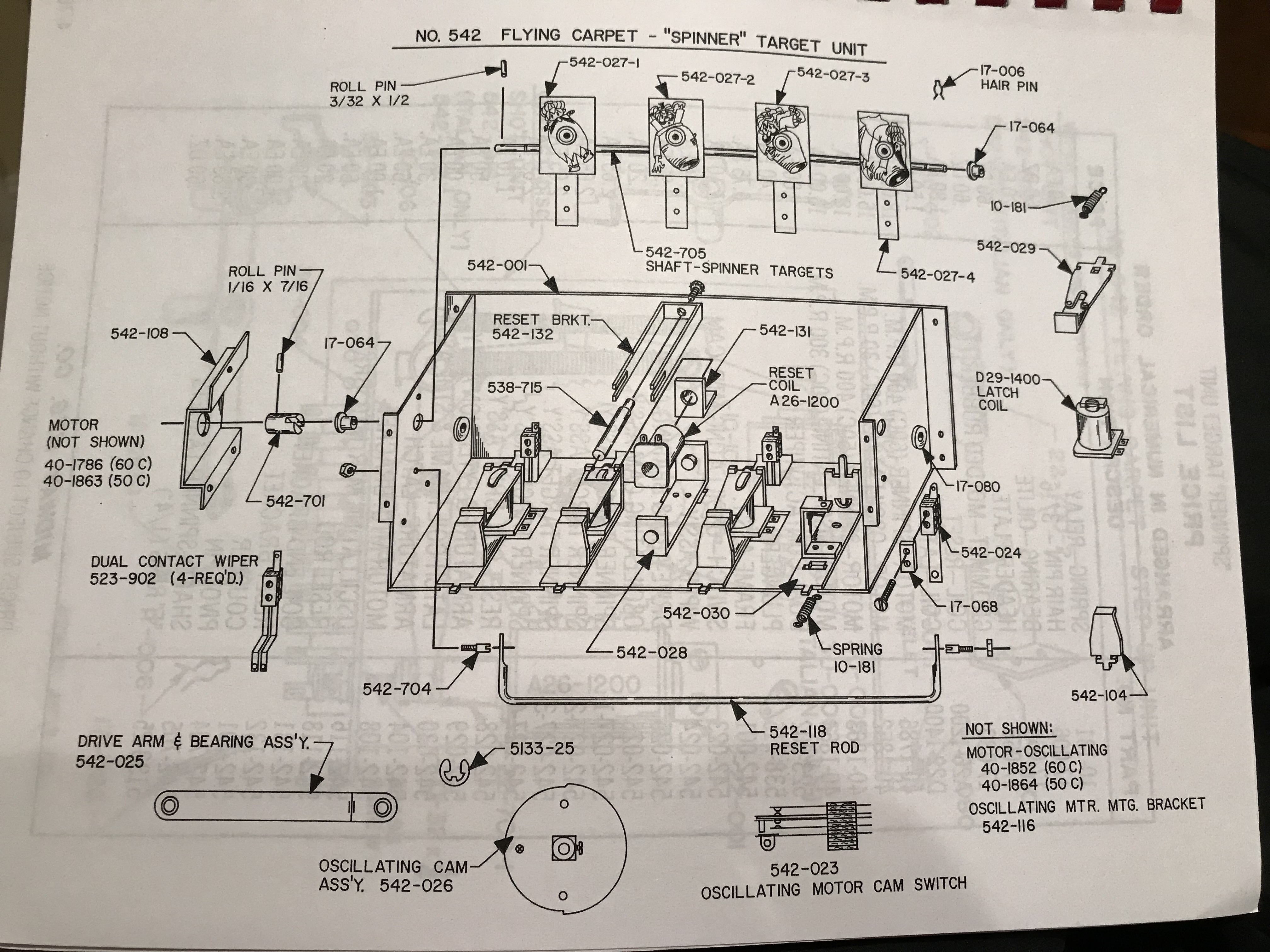
Stationary Target Assembly (this is somewhat different than flying saucer)
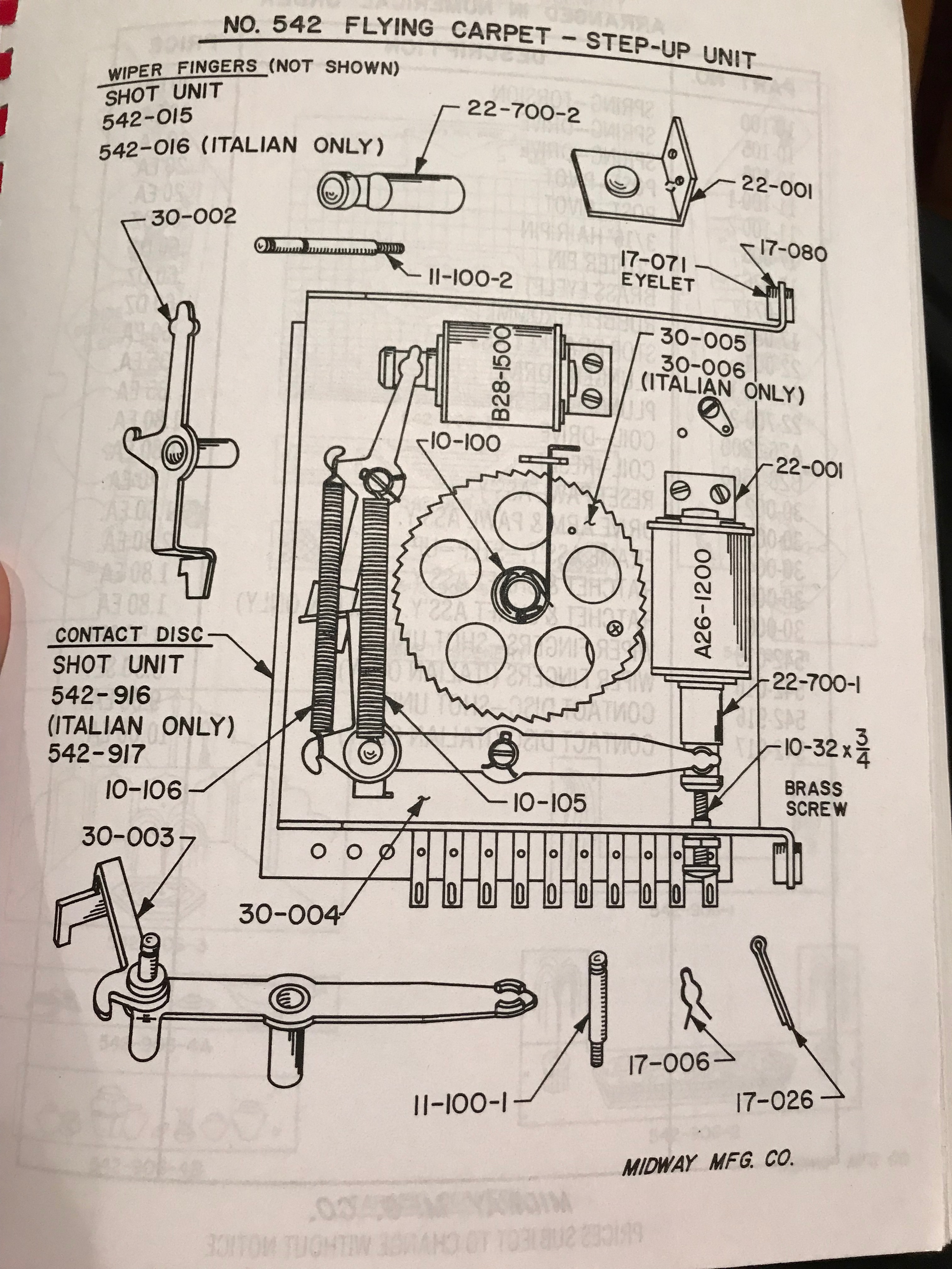
Step Up Unit
More Background
I was looking for a game that had a nice mix of theme and complexity. I wanted one that had a western or space theme, and one that wasn’t too simple in terms of the targets.
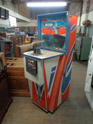
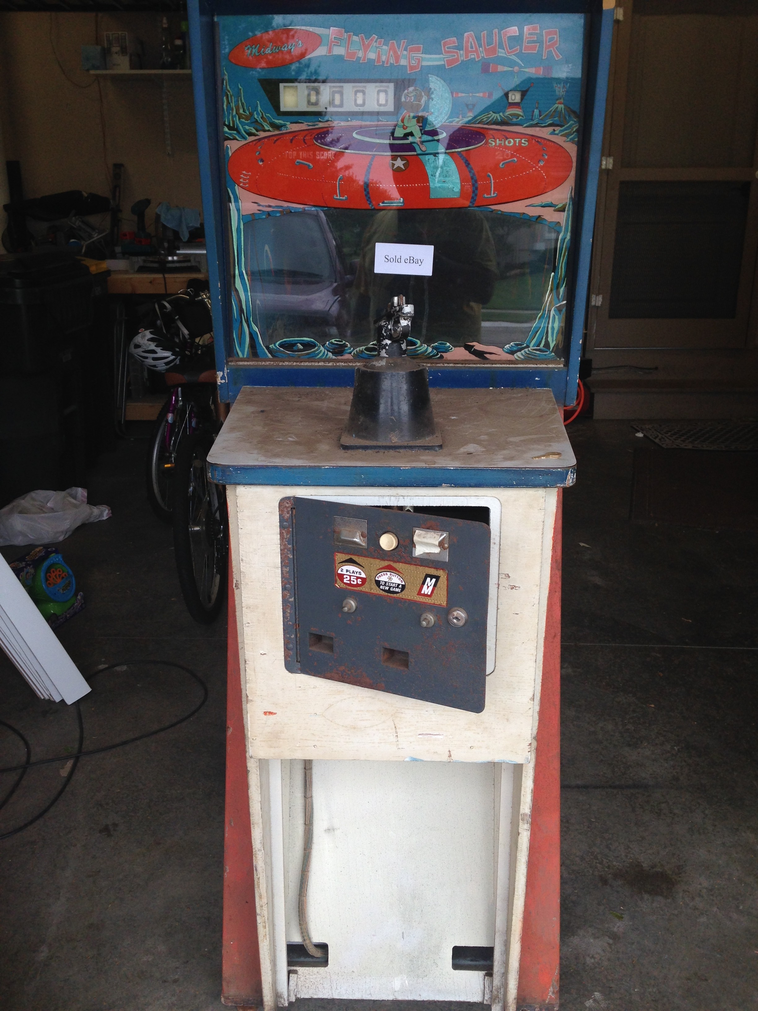
This one seems like a good compromise, and I thought it was in decent shape, although it was non-working. This was an ebay purchase, and too far away to see before purchasing so I bought it on a leap of faith. This came from from coinopwarehouse on ebay. Here’s the ebay pictures.
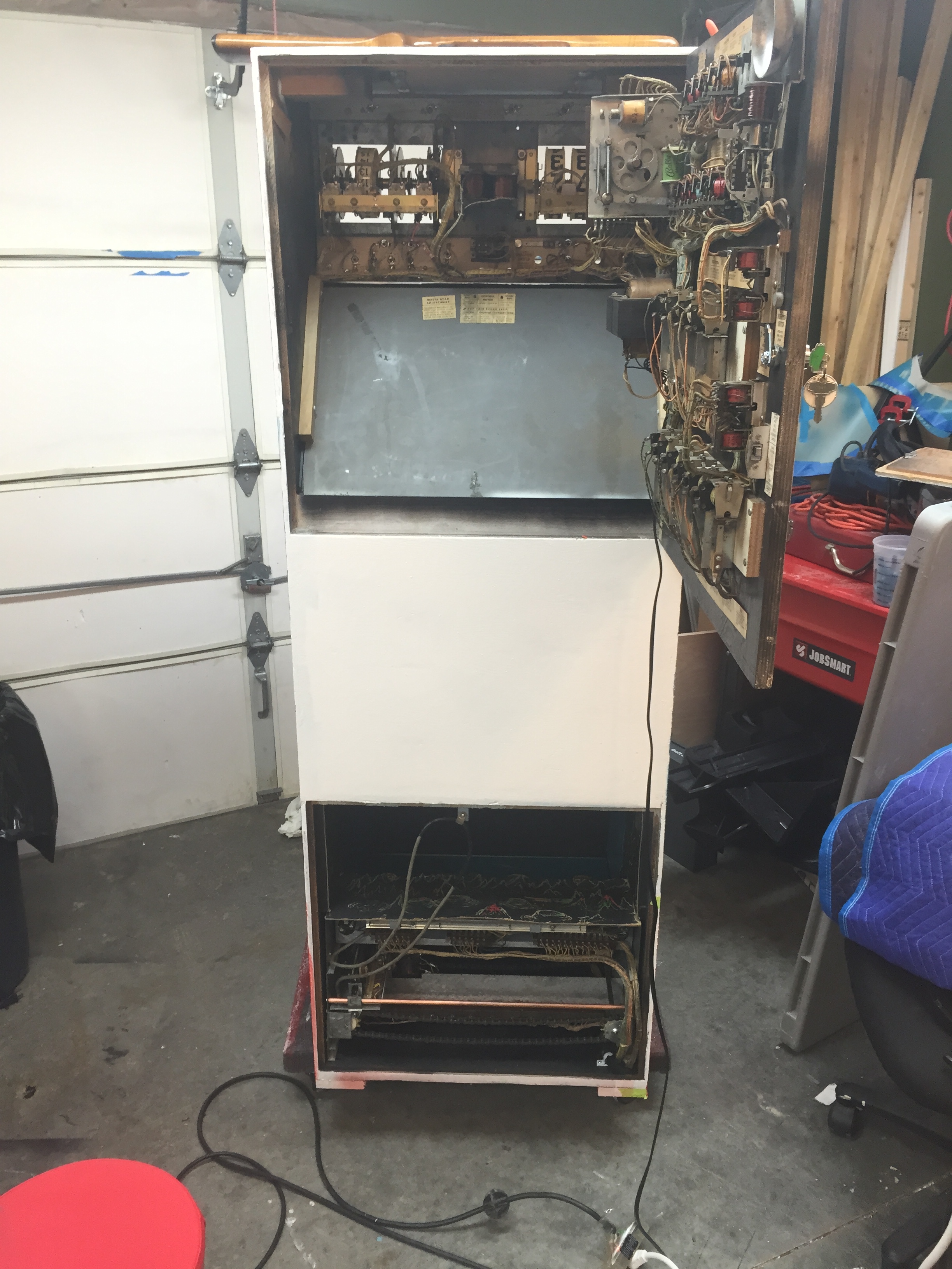
Arrival and Initial Assessment
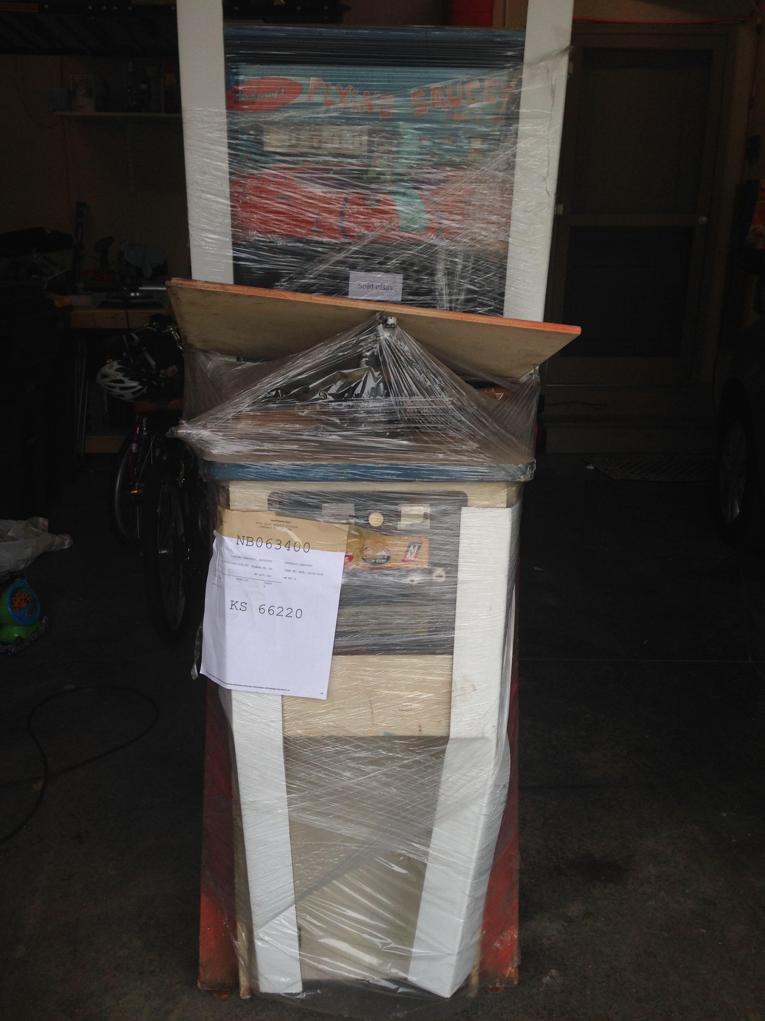
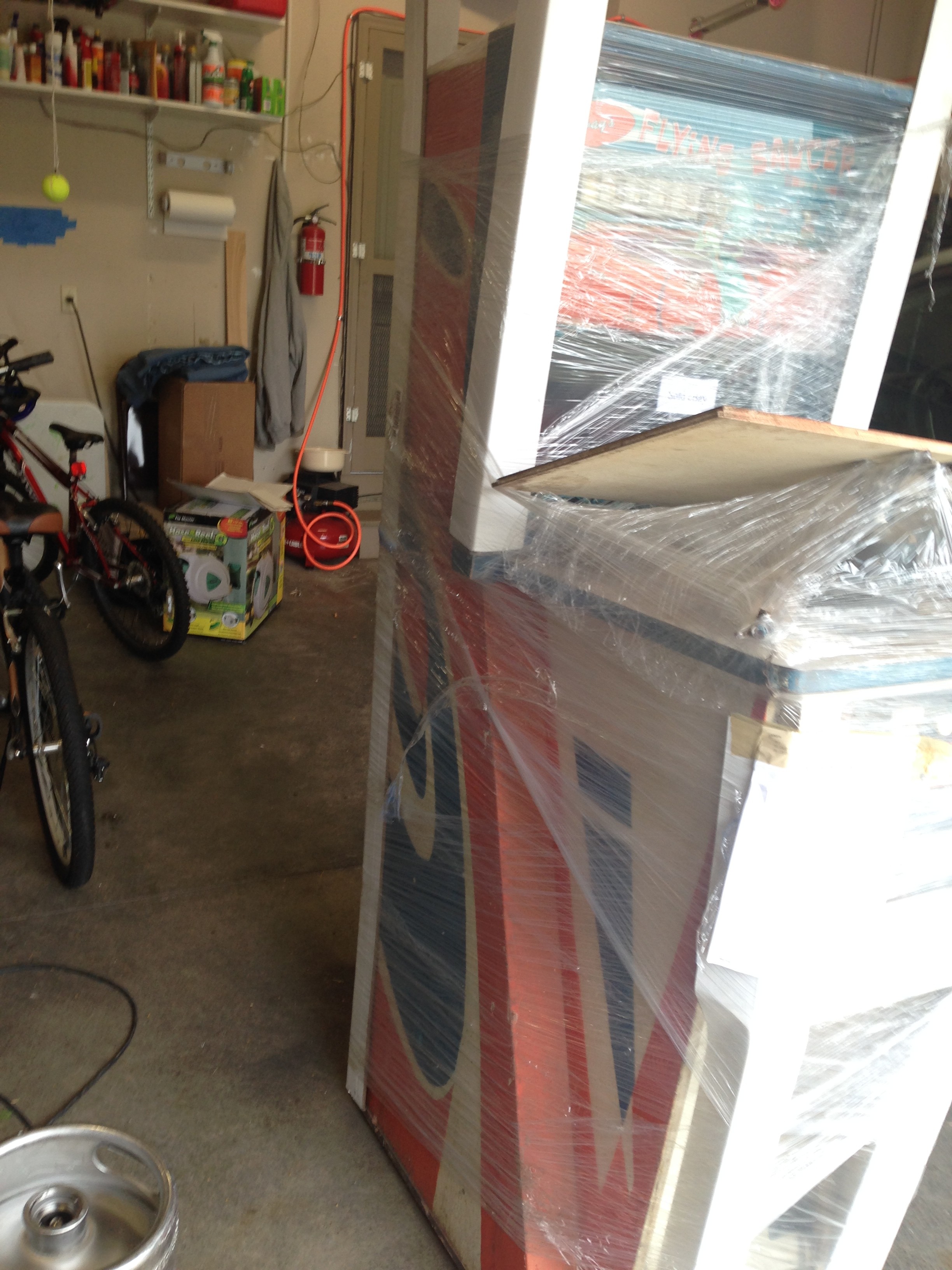
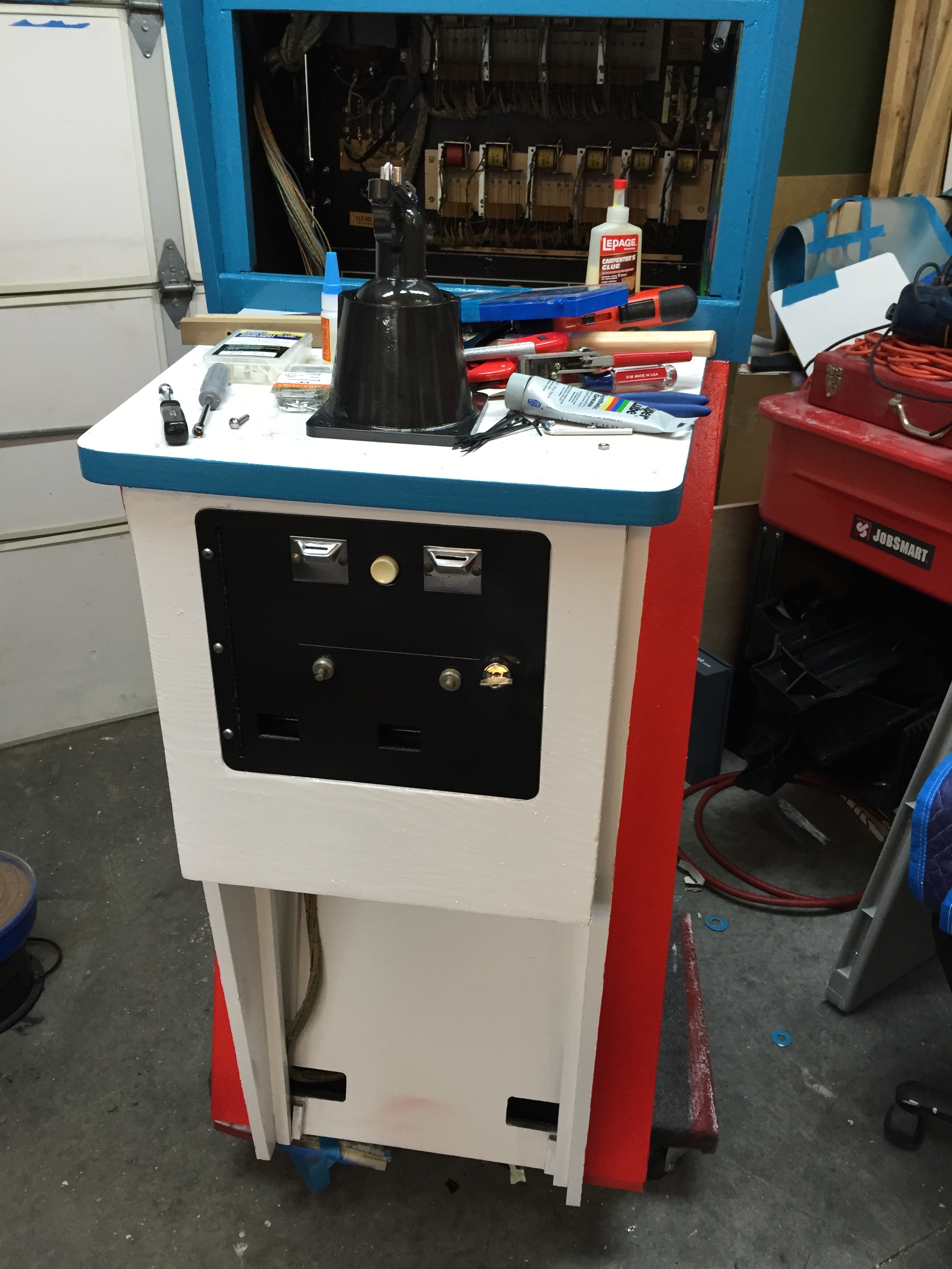
Well, it arrived. NAVL/STI did a pretty good job. No damage noted in transit. Dirty and stinky!
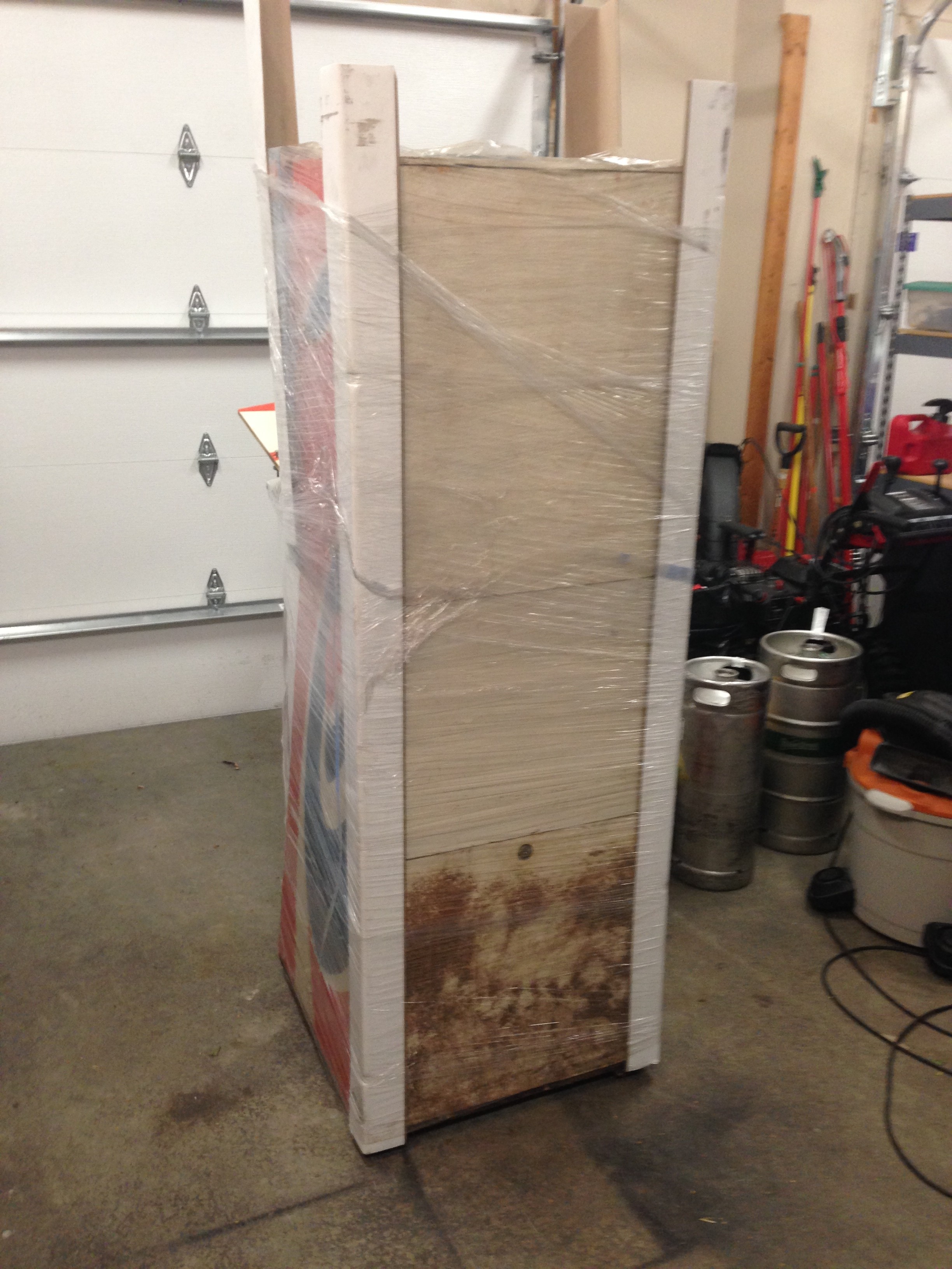
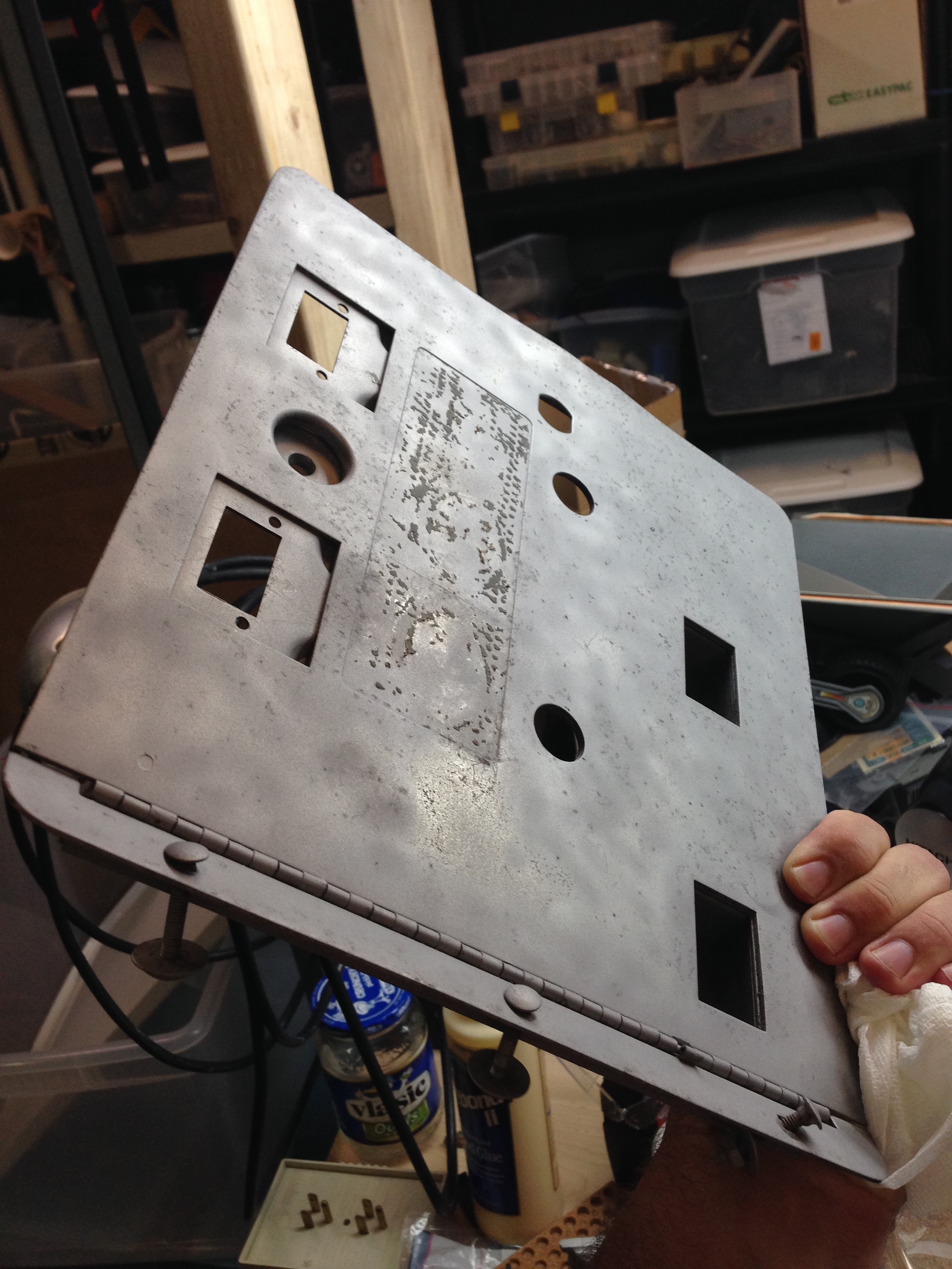
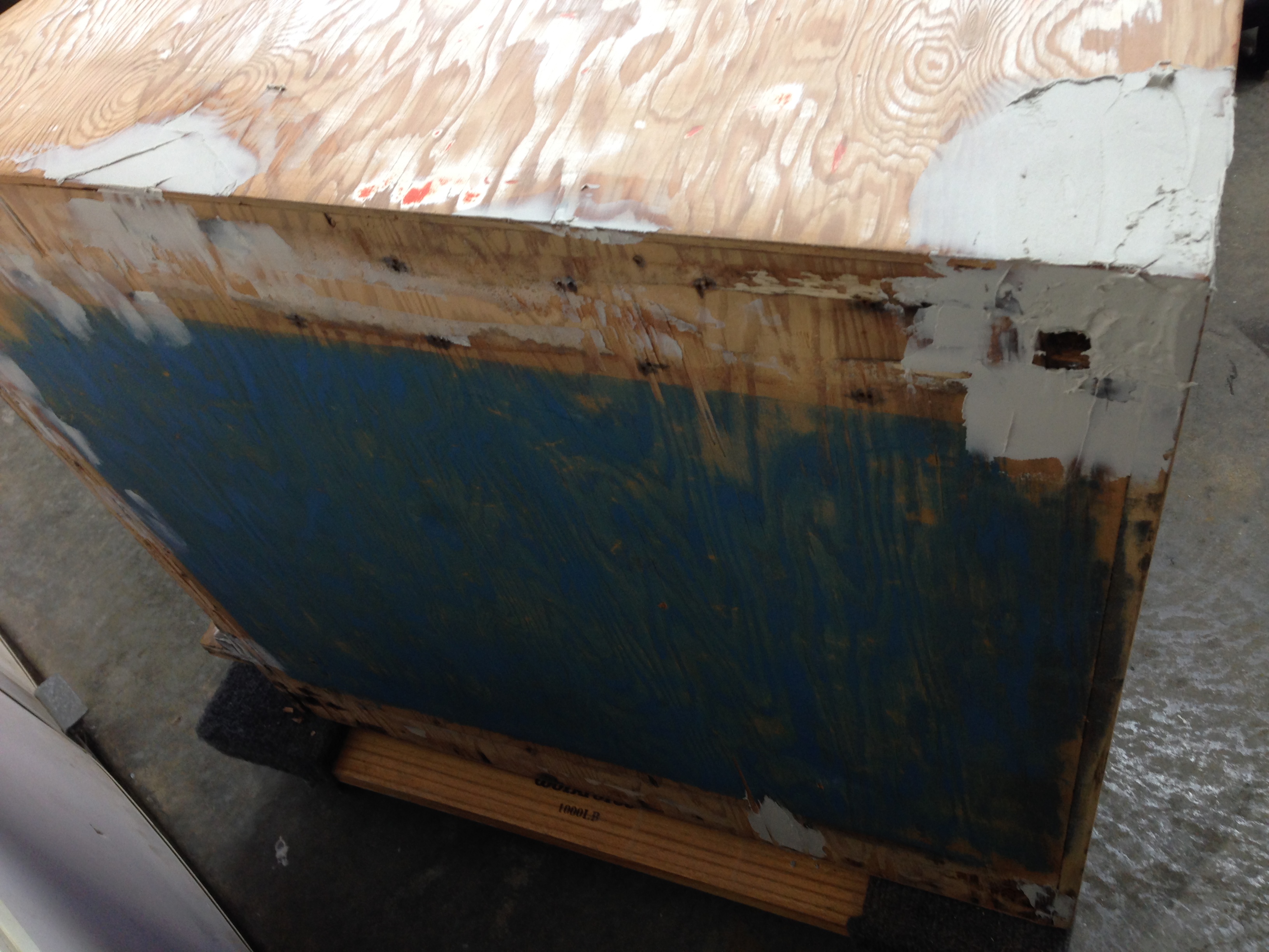
The back of the bottom back panel looks pretty bad. I’m not sure what kind of staining this is, it’s not mold. It looks like some kind of bleed through, but I think it will sand off pretty well.
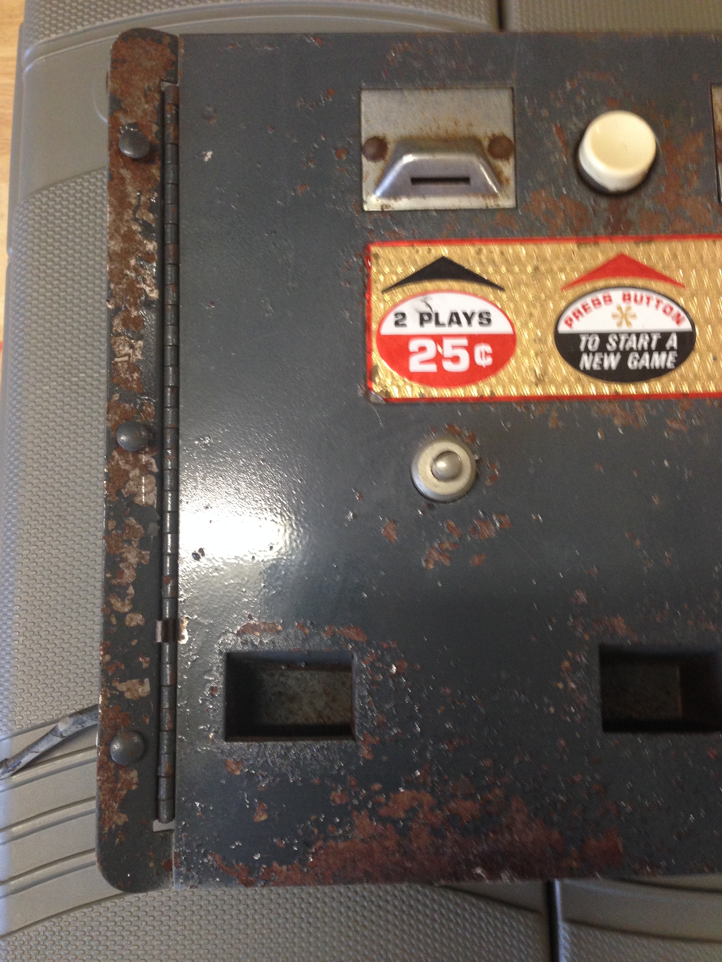
It is very, very, dirty and stinky. It must have been sitting in a barn or shed for quite some time. The coin door is rustier than I thought, and I think it will have to be blasted and re-painted. I don’t think I can save the sticker, but cannot find another like it so far. If anyone knows where to source one it would be greatly appreciated. It’s a foil type sticker. I’ll add a closeup of it.
Update: I found John’s Jukes has some NOS Midway parts, and I ordered a replacement sticker for the coindoor from him. I think he may be the only source! http://www.flippers.com/catalog/product_info.php/decal-play-plays-p-764
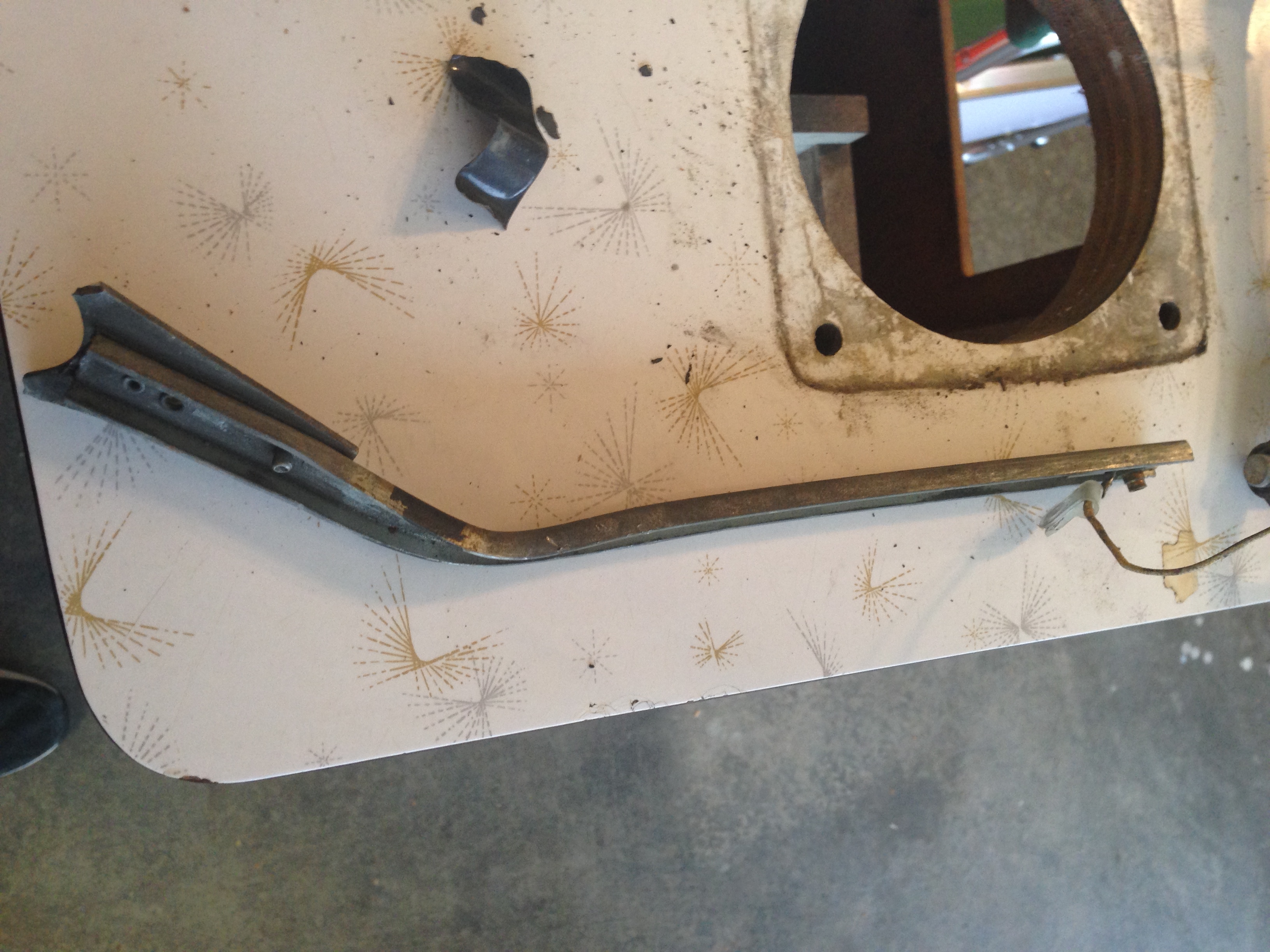
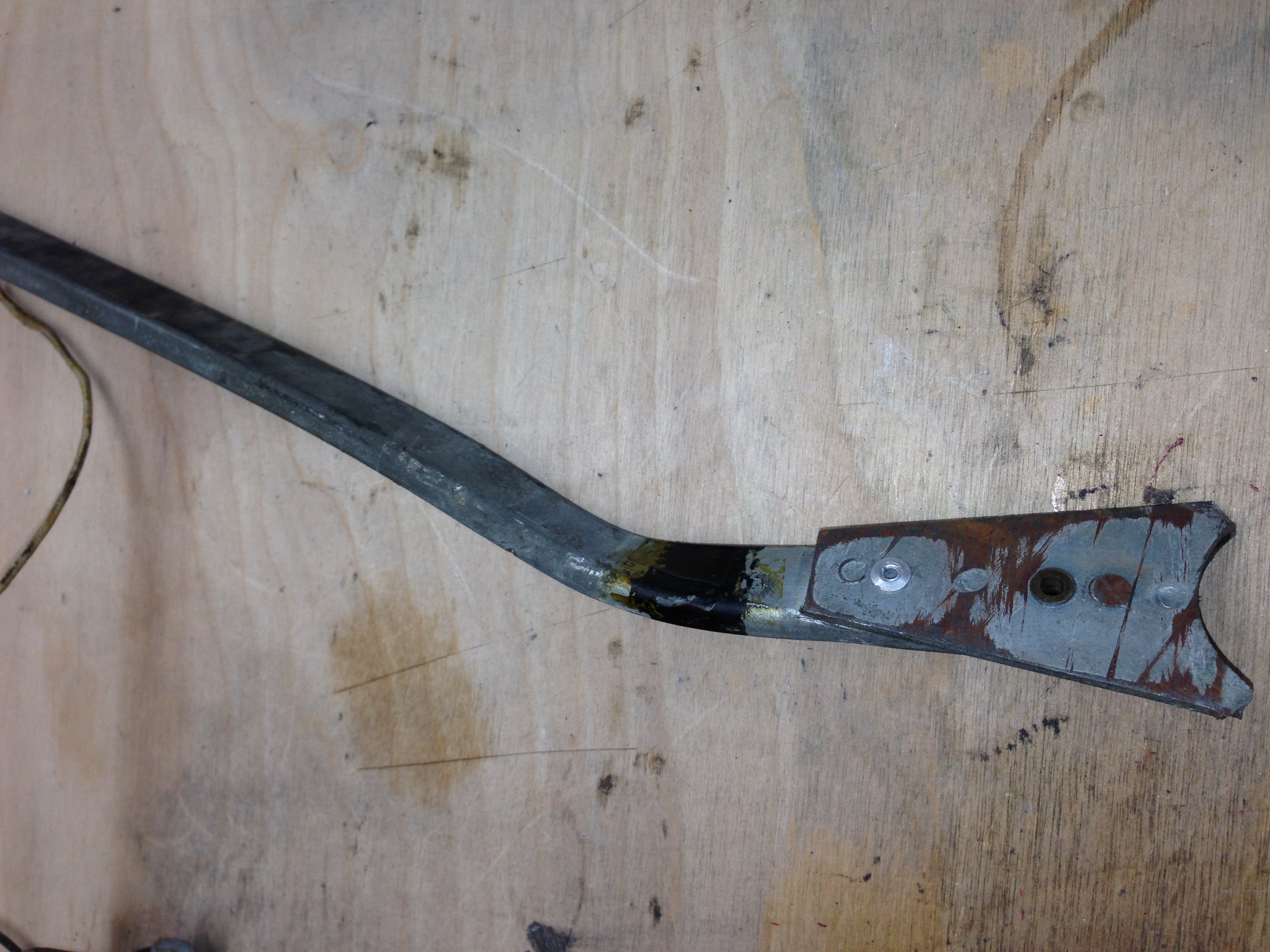
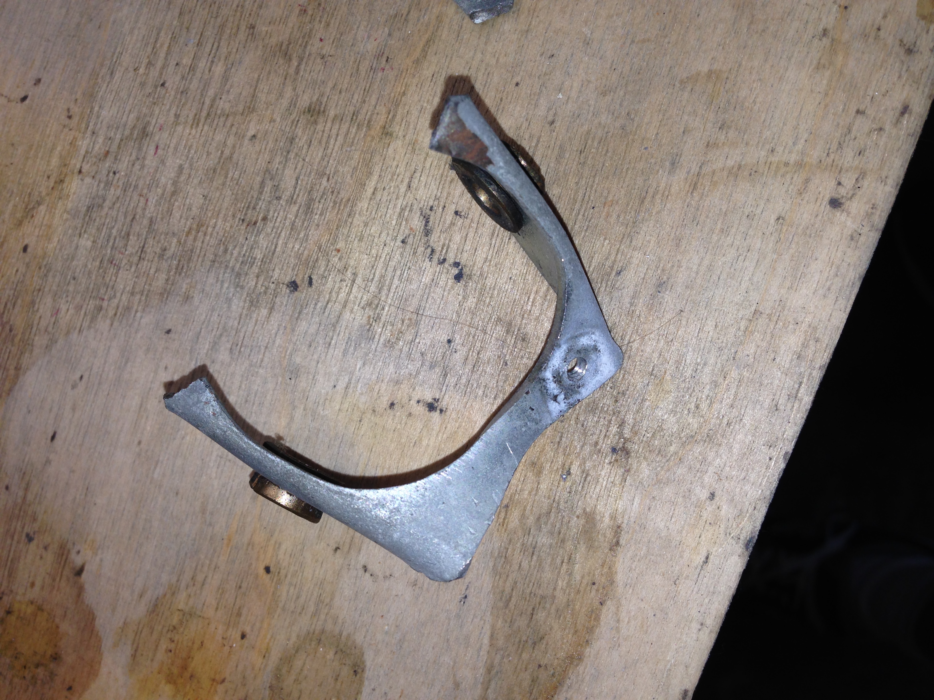
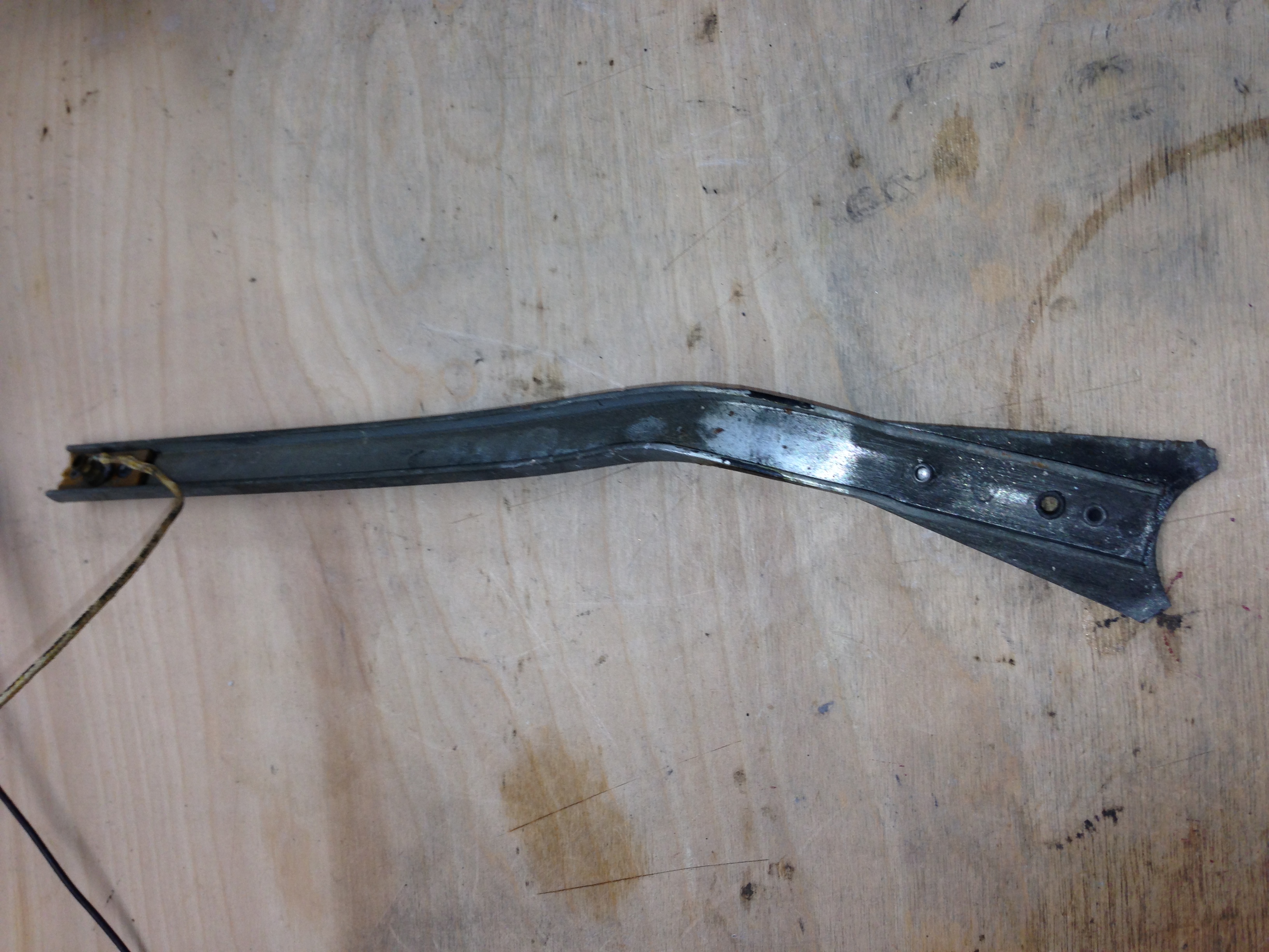
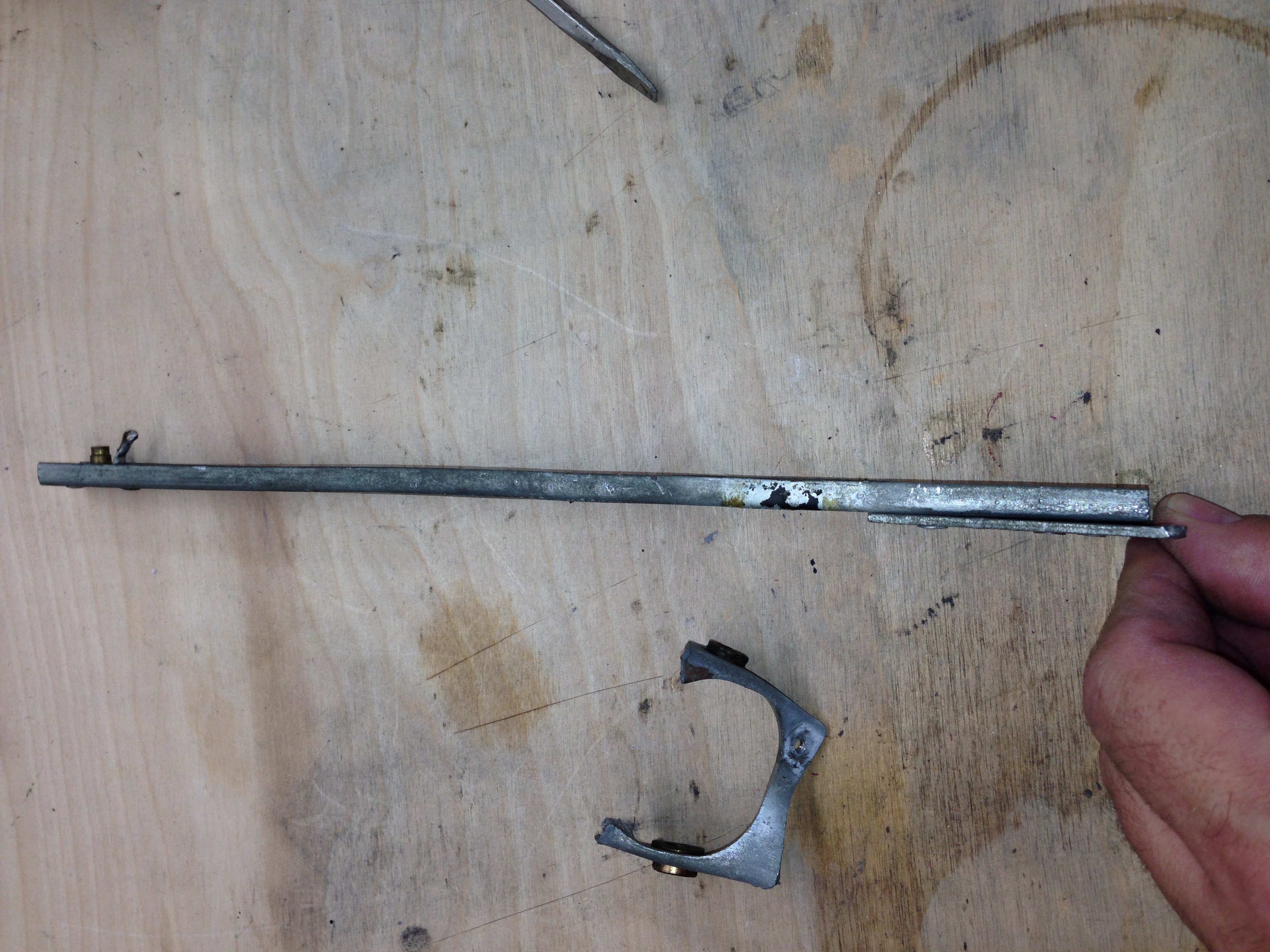
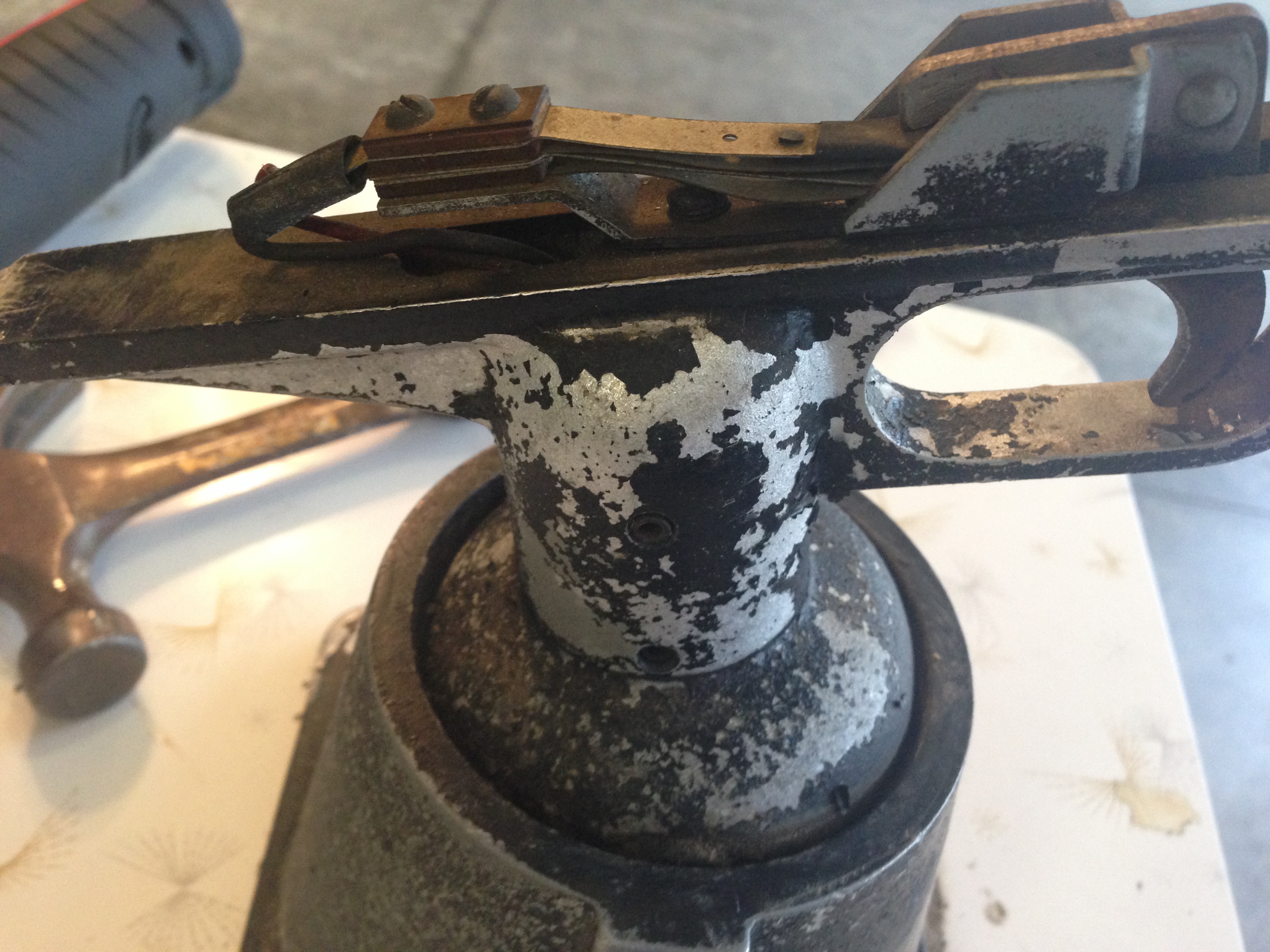
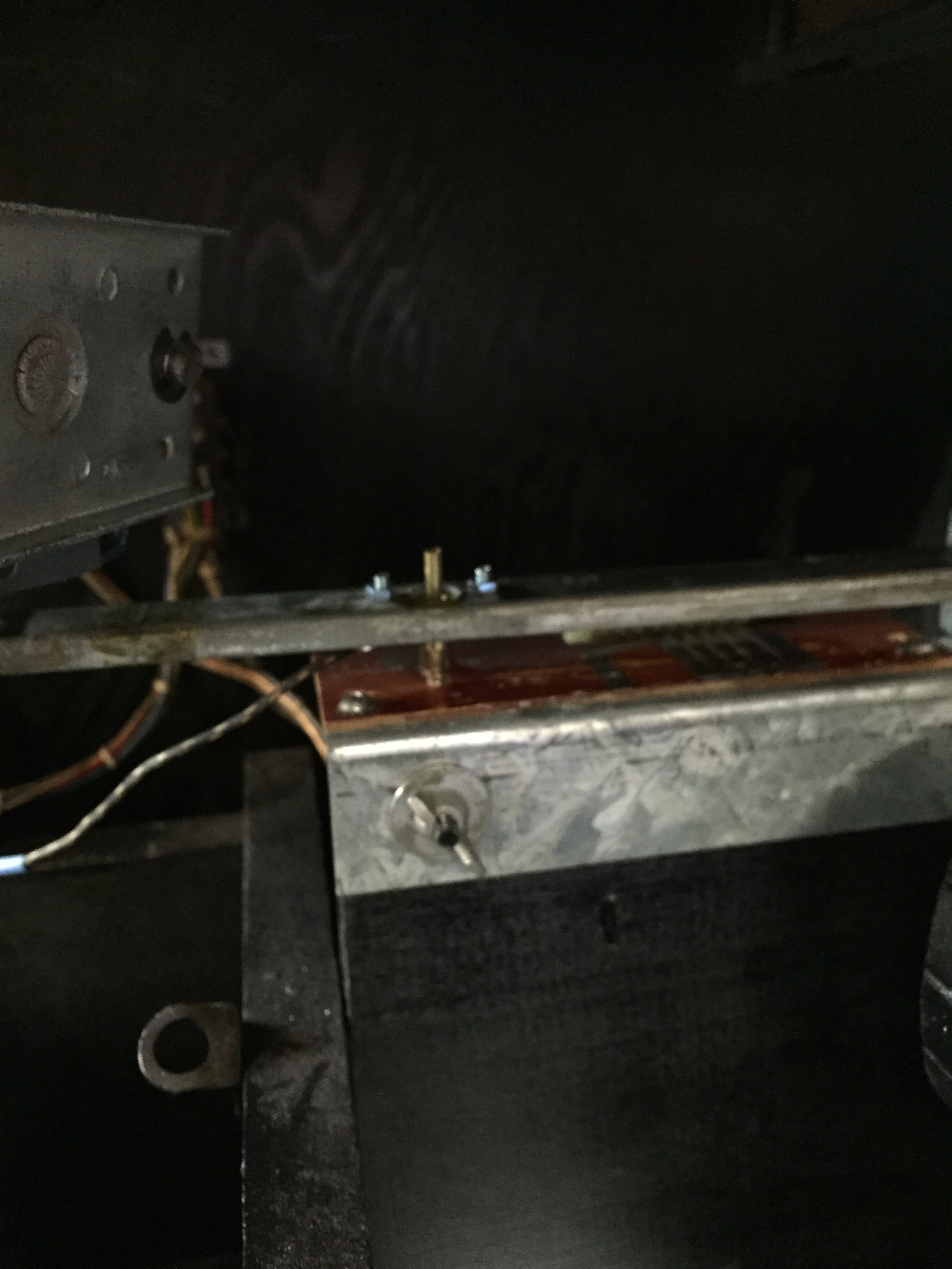
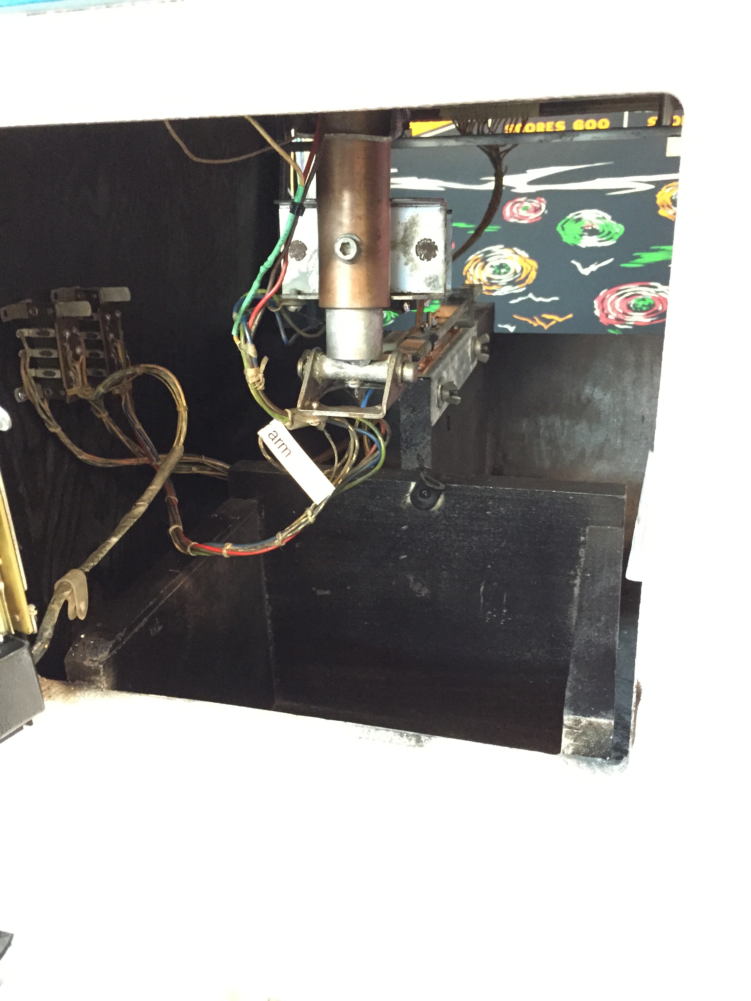
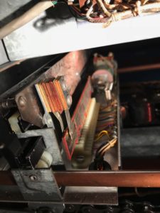
The main problem I see with it is that the gun assembly has been pretty abused. The “up/down” movement seems in good shape, but the “right/left” arm is bent/broken off. Here’s what it looks like.
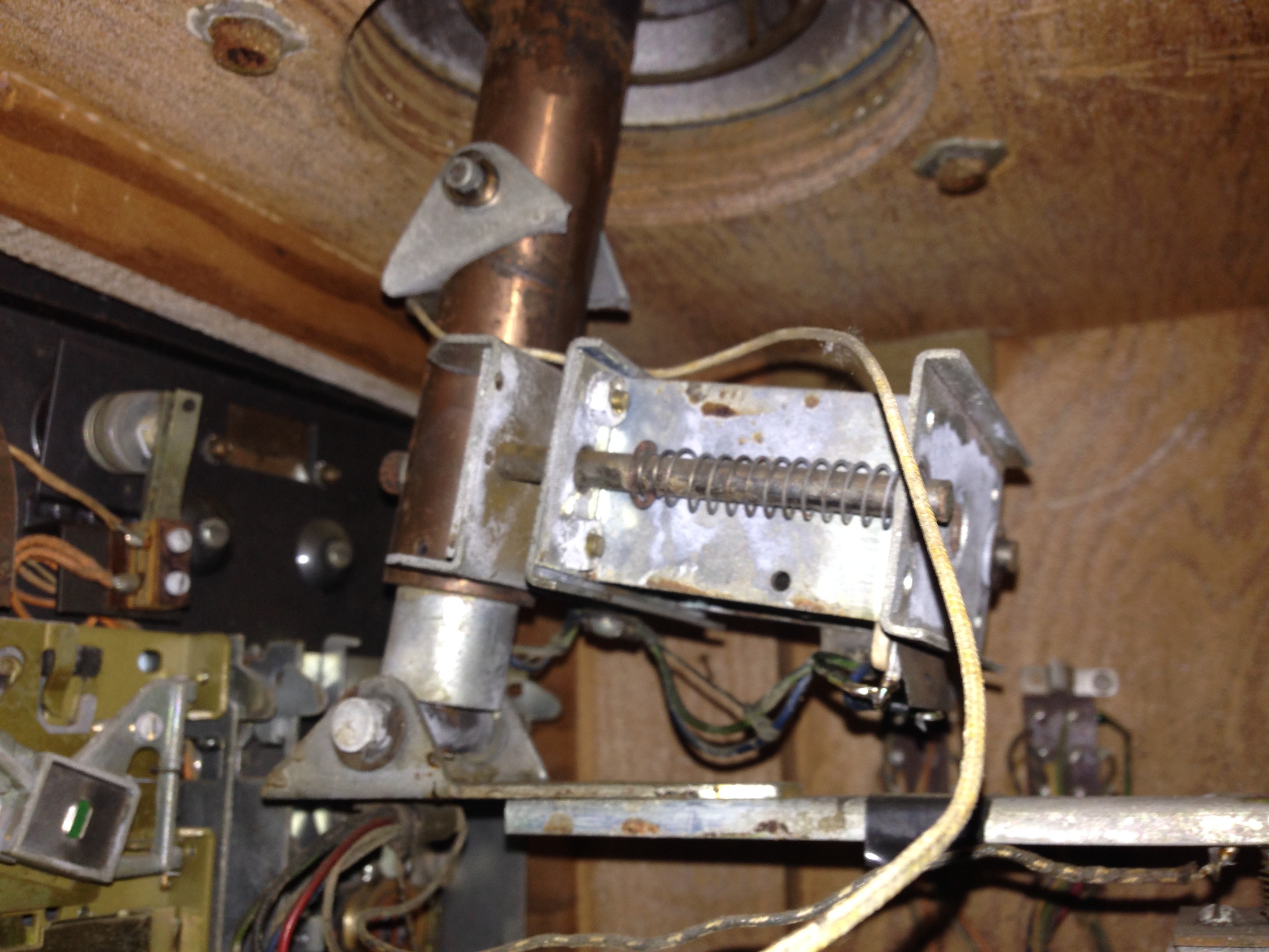
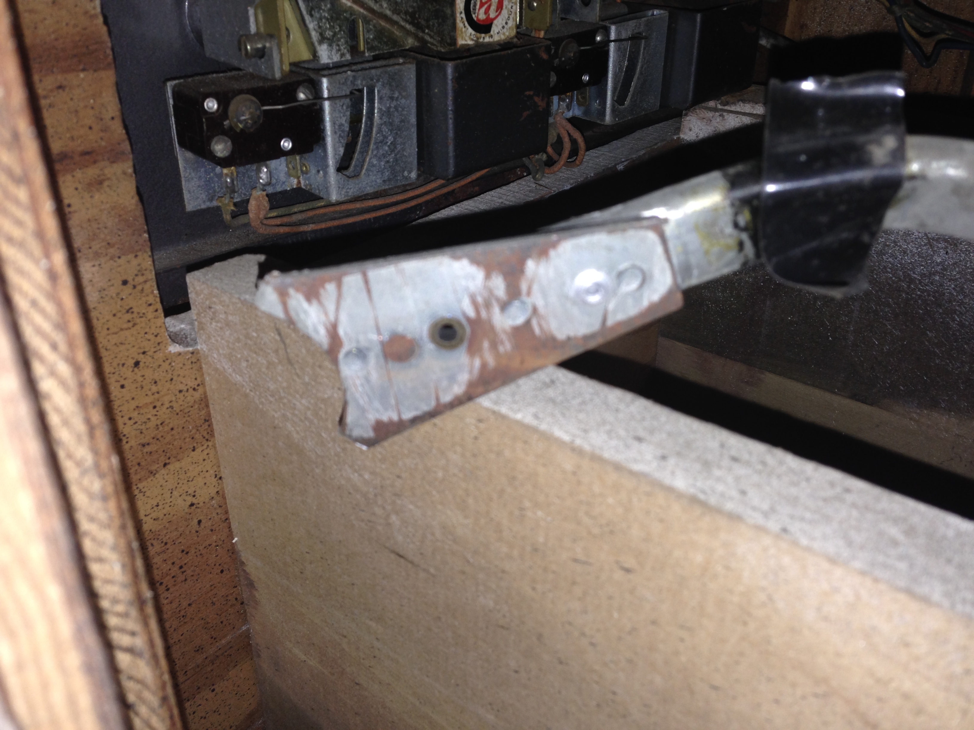
In the first picture you can see the bracket the arm was attached to at the top of the bar coming down from the gun assembly above. In the second picture you can see the arm and how bent it is. In the third, there is a close up of the part that broke off the gun assembly.
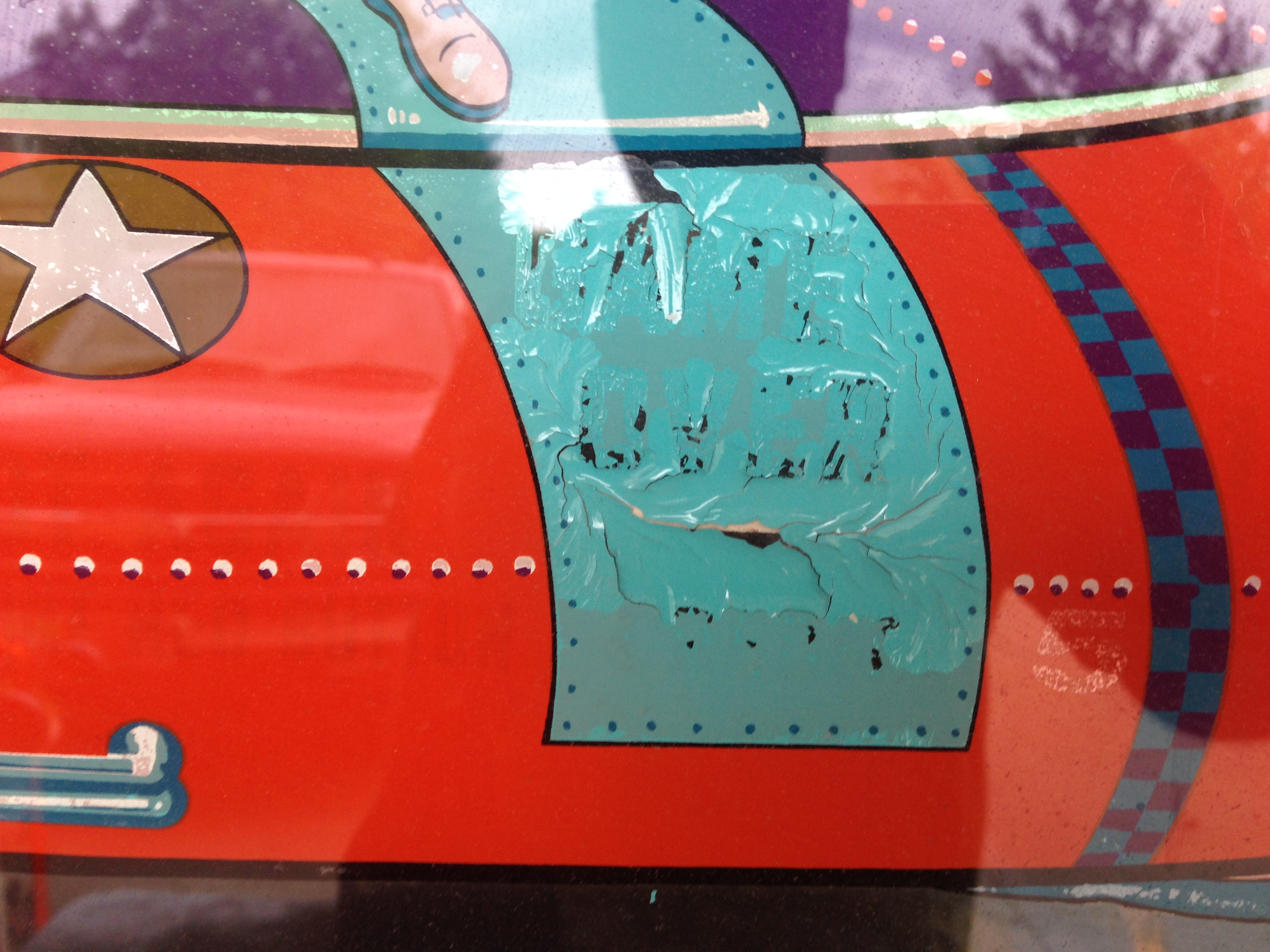
There is some minor flaking from the backglass, and some moderate flaking from the glass at the back of the target assembly. I will seal this with Krylon Triple Thick as soon as I get it apart.
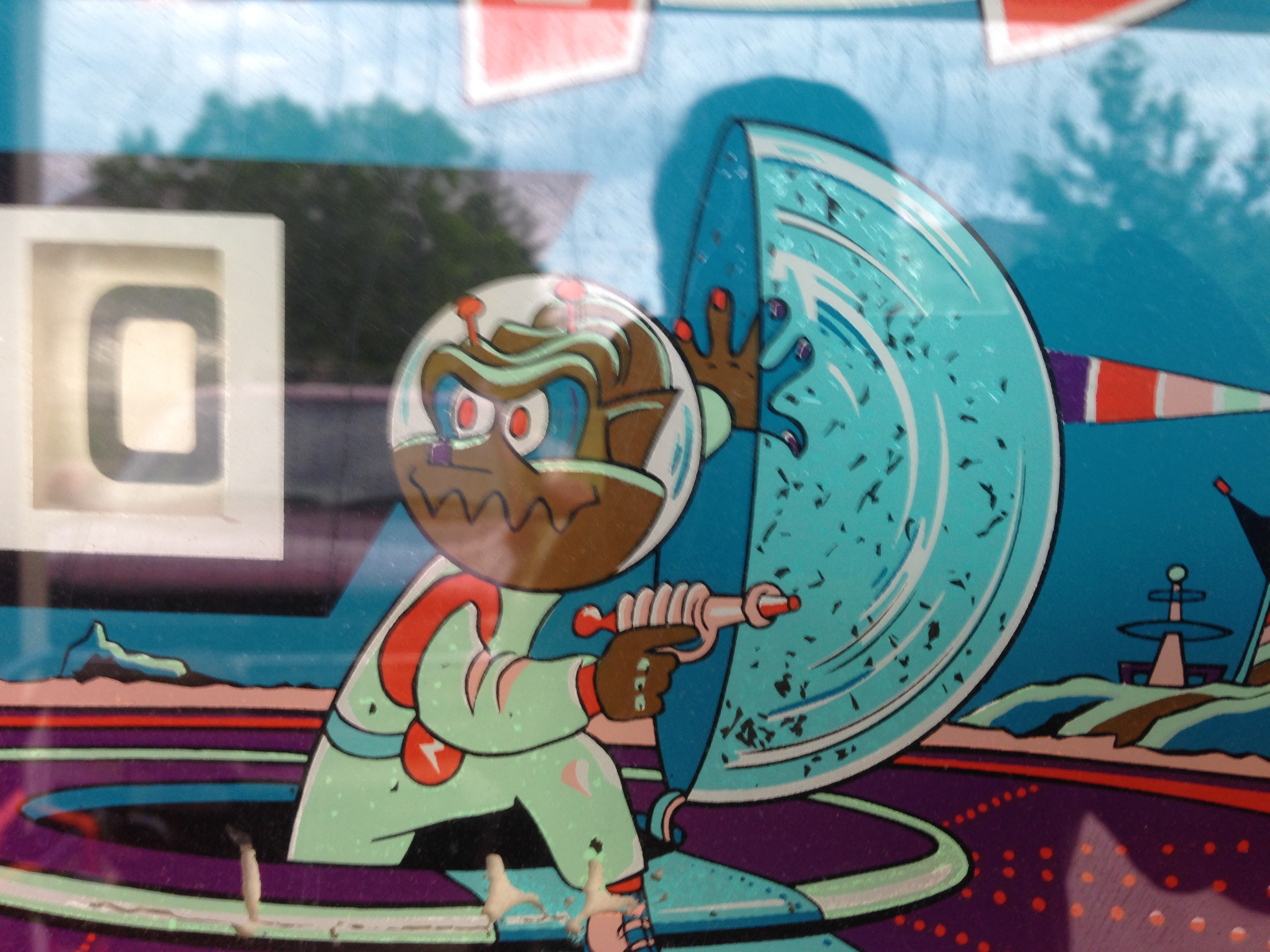
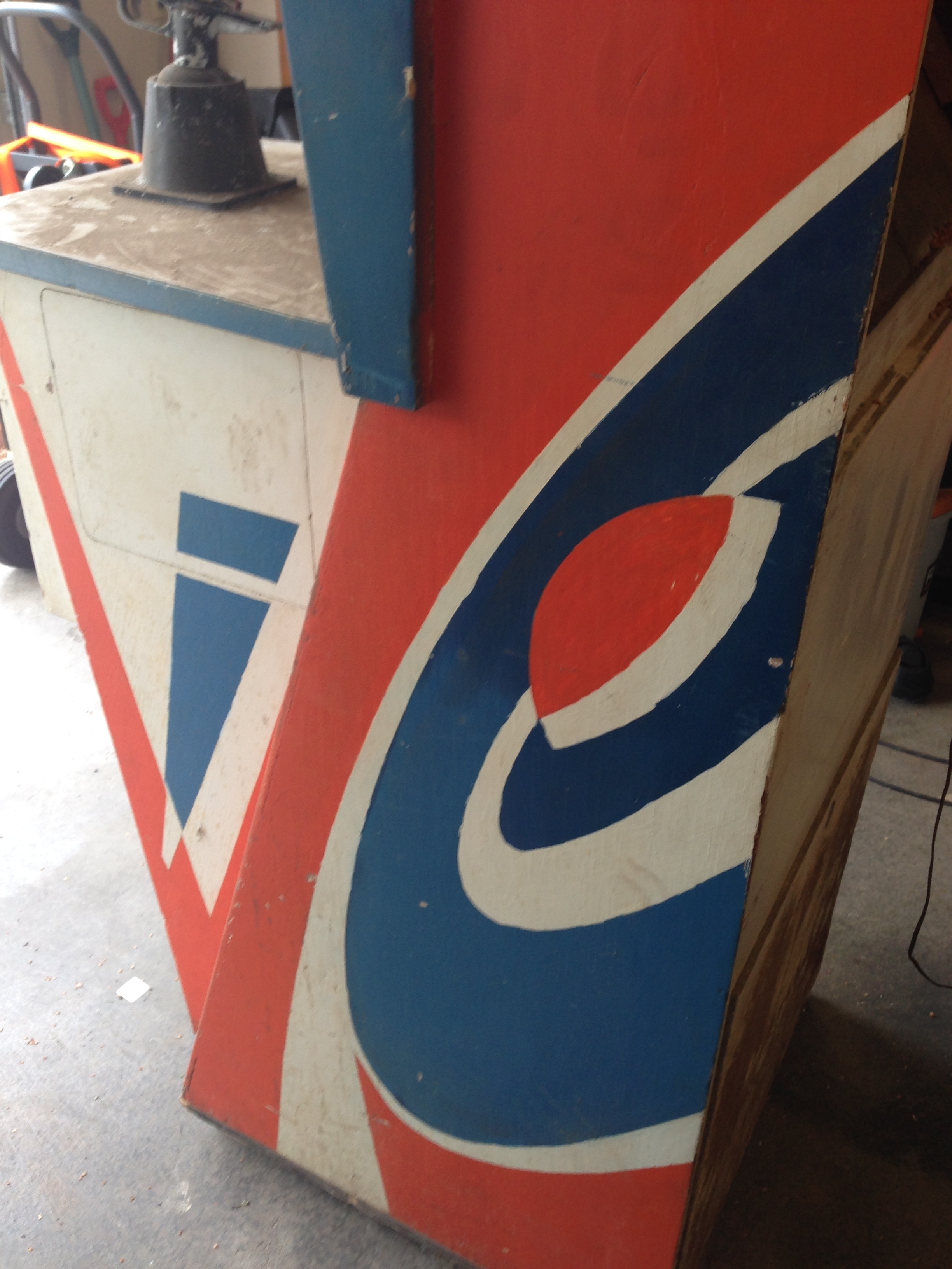
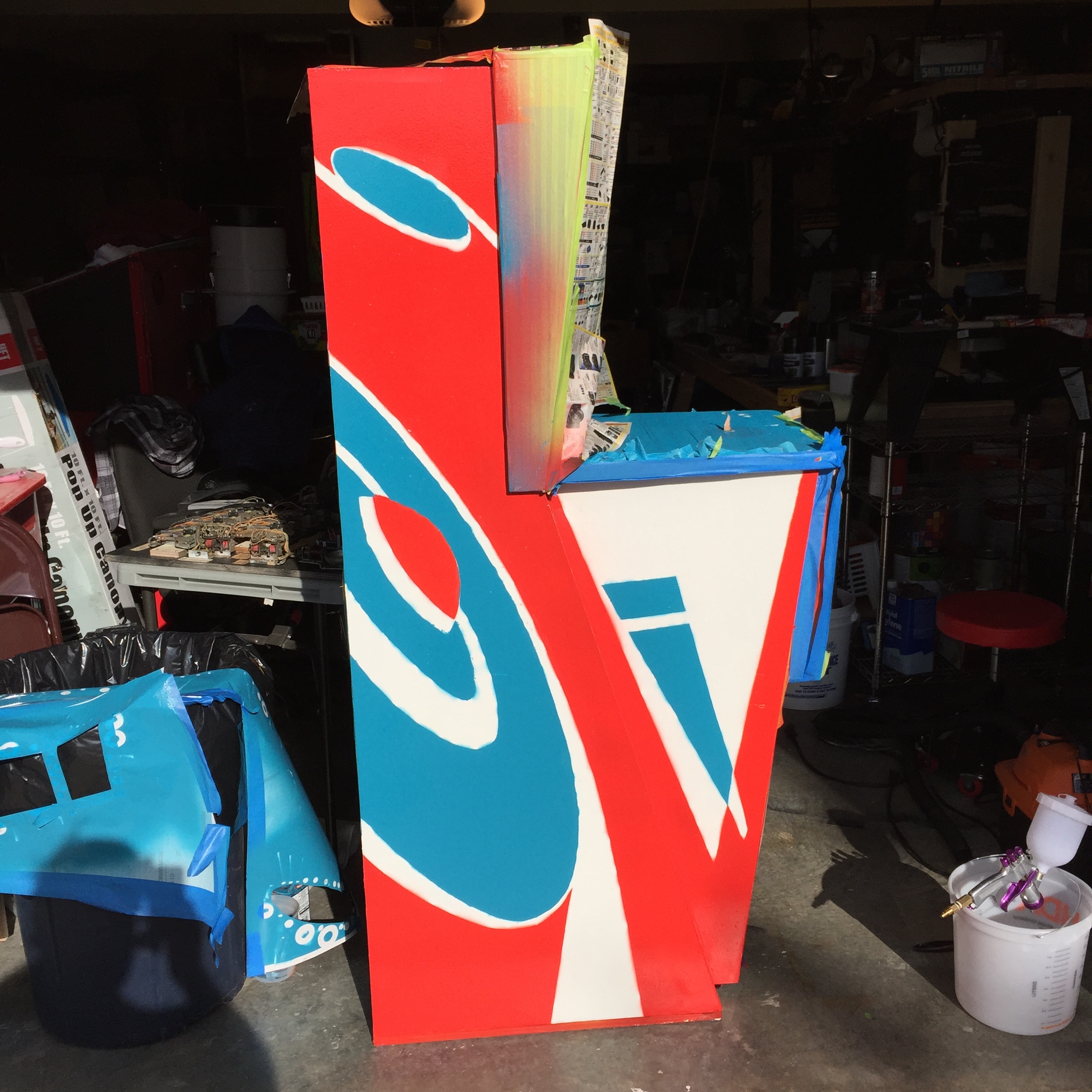
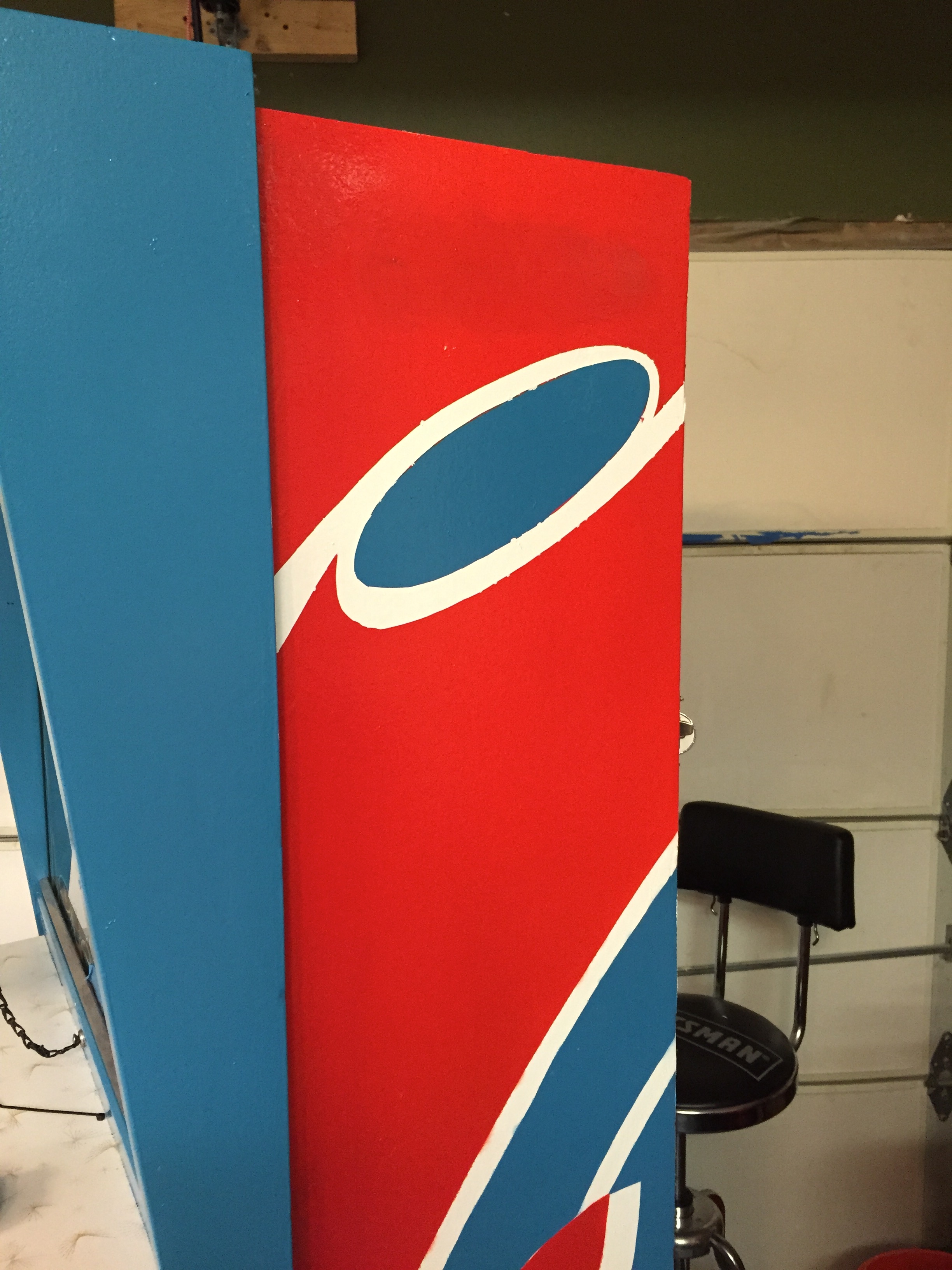
The cabinet has been “touched up” a bit. Have a look at the cap of the saucer, don’t know if you can tell from the picture, but basically someone has “painted in the lines” to touch up this cabinet. It’s not too bad, but I think I might have to do stencils and repaint the cabinet at some point otherwise this will drive me crazy.
Areas Needing Work
- Cabinet – Needs wood filler, sanding and repainting
- Clean and repair cardboard targets and background
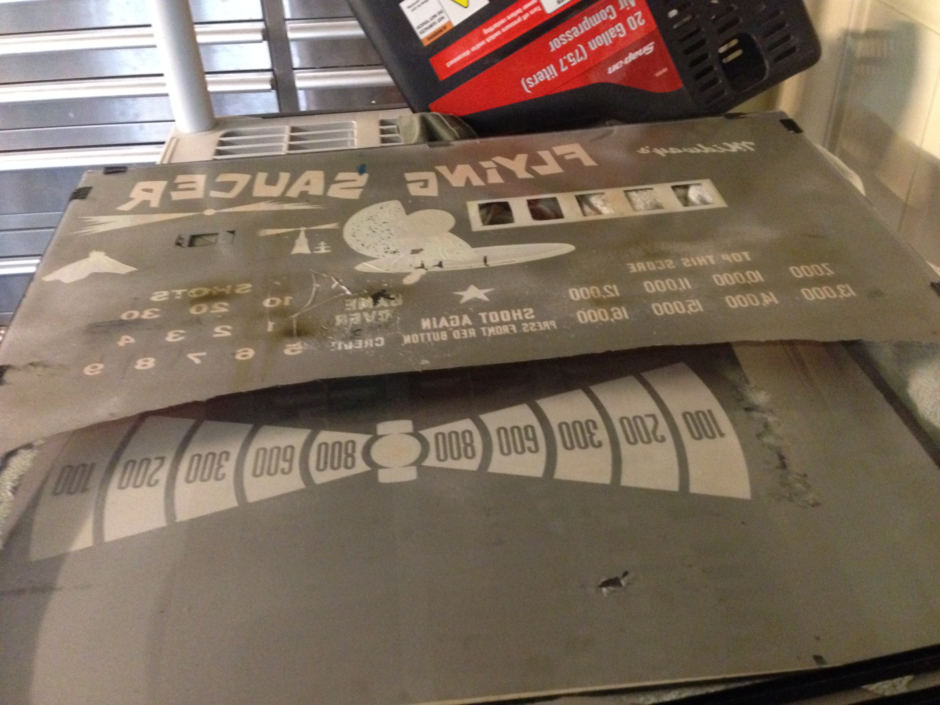
- Backglass and bottom glass – need sealing, and perhaps reproduced
- Check relays – clean, adjust, and repair as necessary
- Check steppers, clean and lube
- Credit Stepper
- Check motors – clean and lube
- Target up/down motor
- Target right/left motor
- Score motor
- Repair gun assembly – weld vertical bracket, clean and adjust, sand blast and repaint
- Gun stock – sand, stain and clear coat
- Gun barrel – sand blast and repaint
- Repair bottom of cabinet – small amount of dry rot on two 1×4 runners
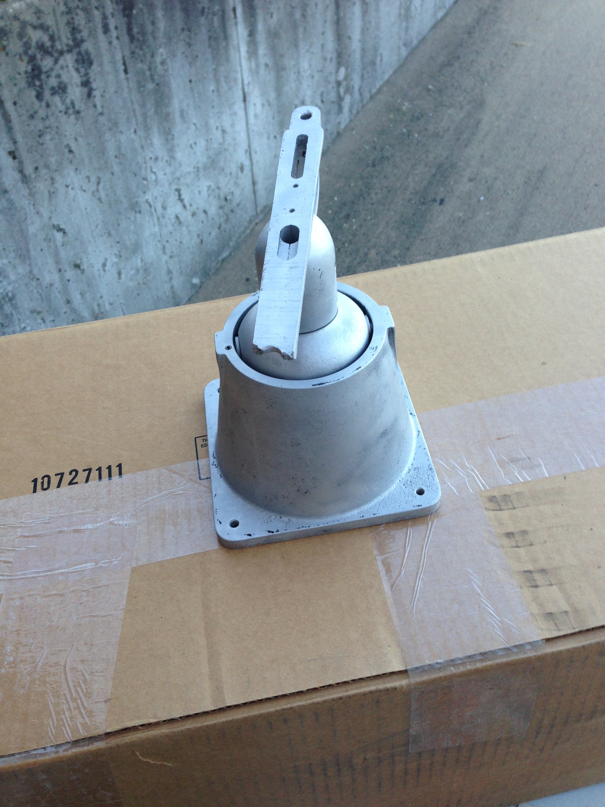
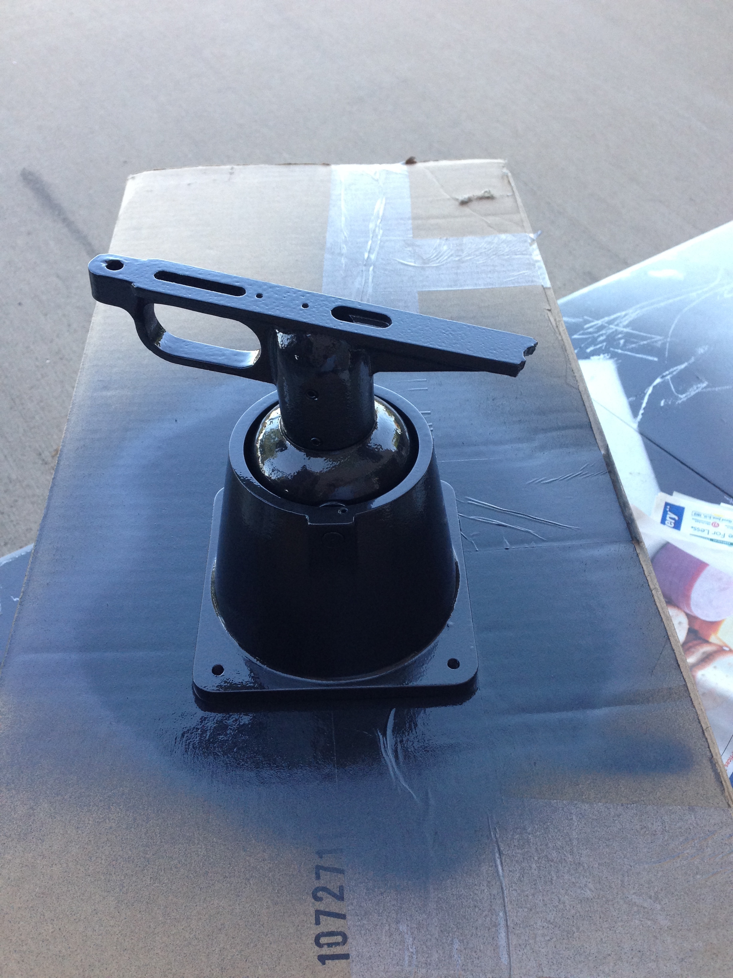
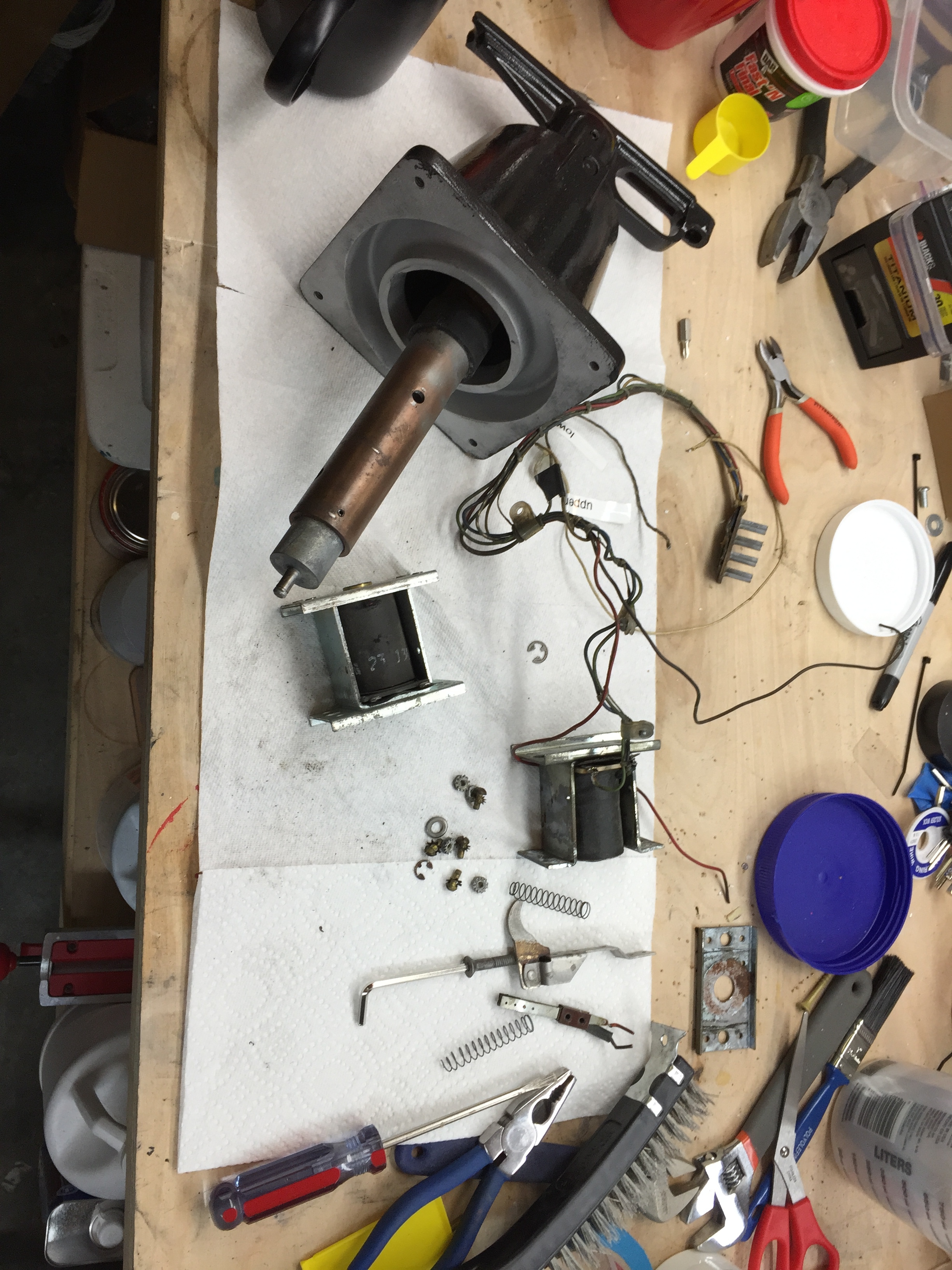
Gun Assembly
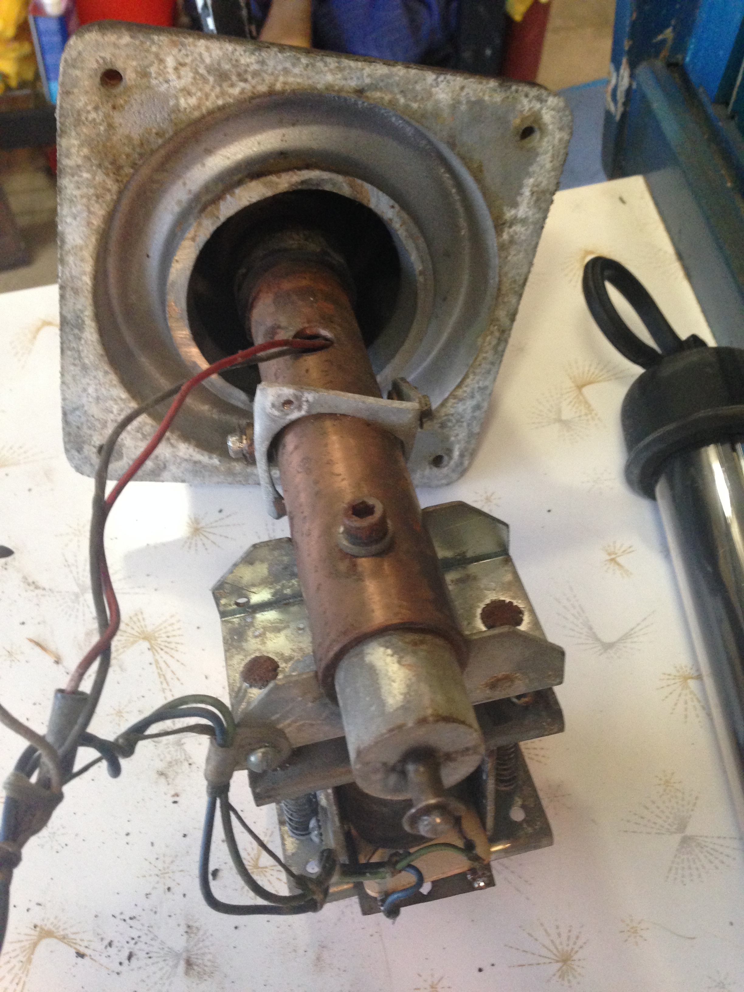
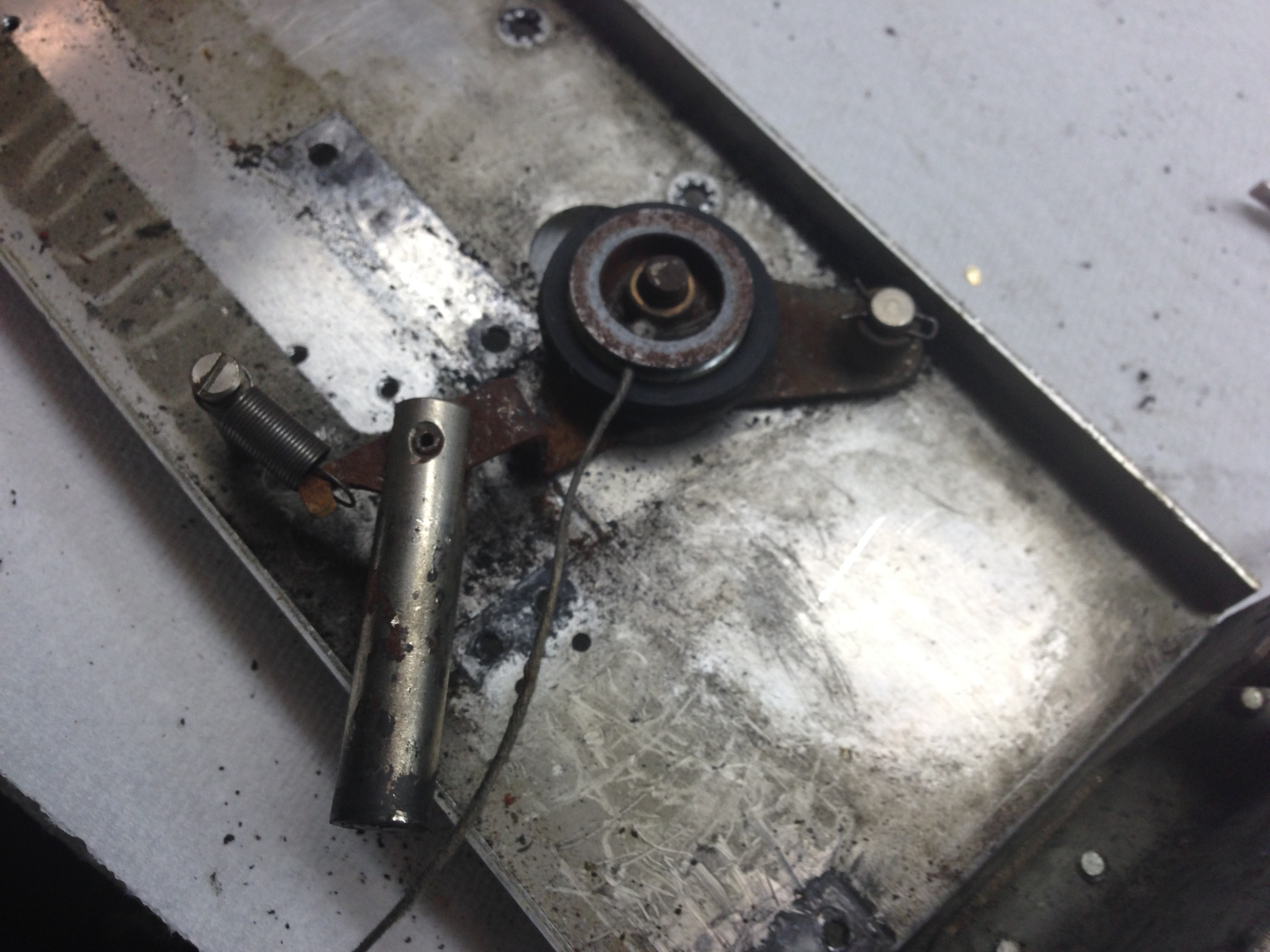
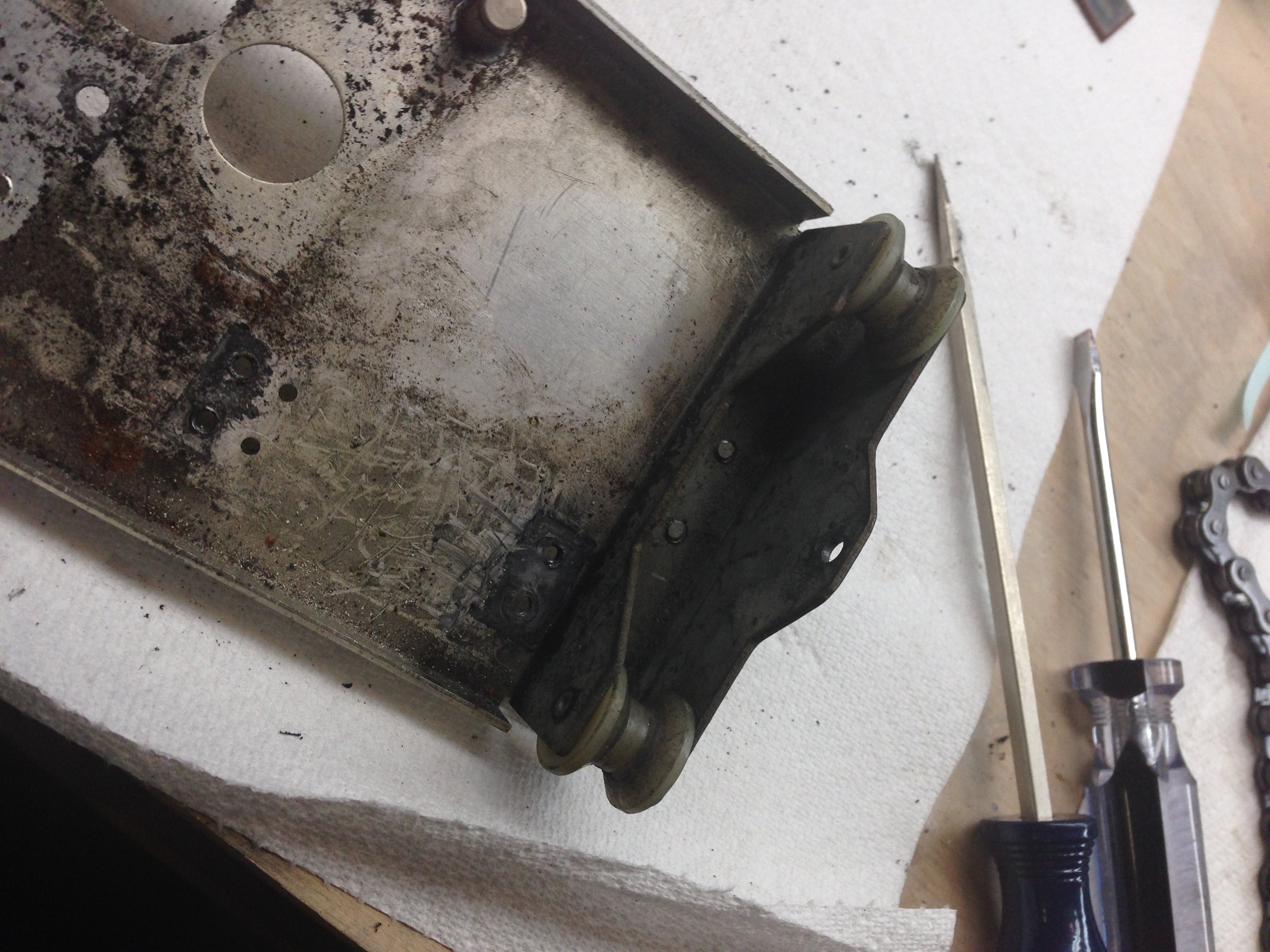
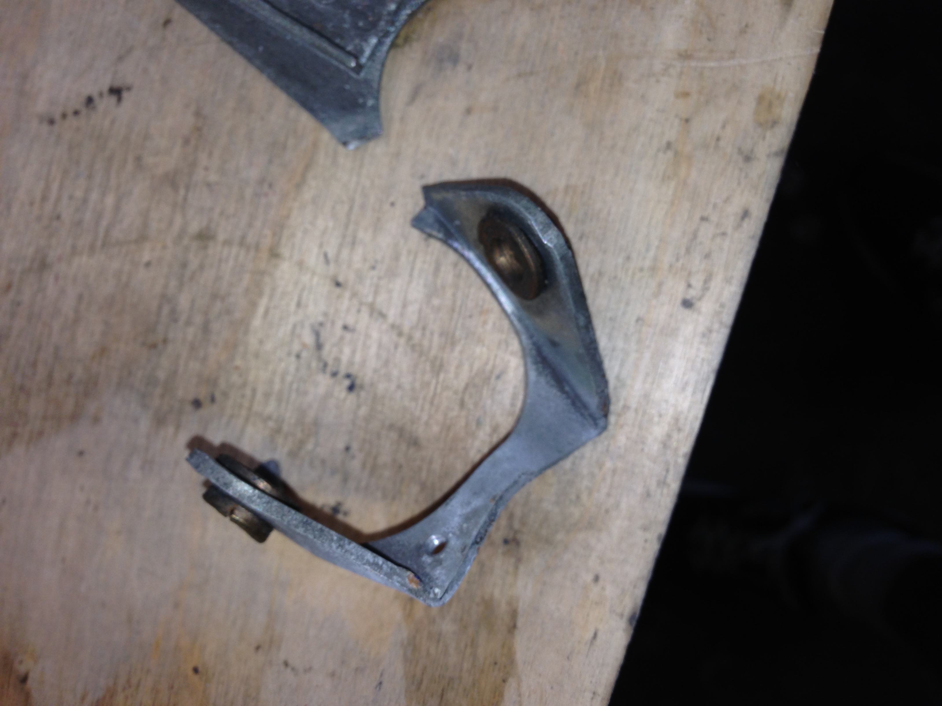
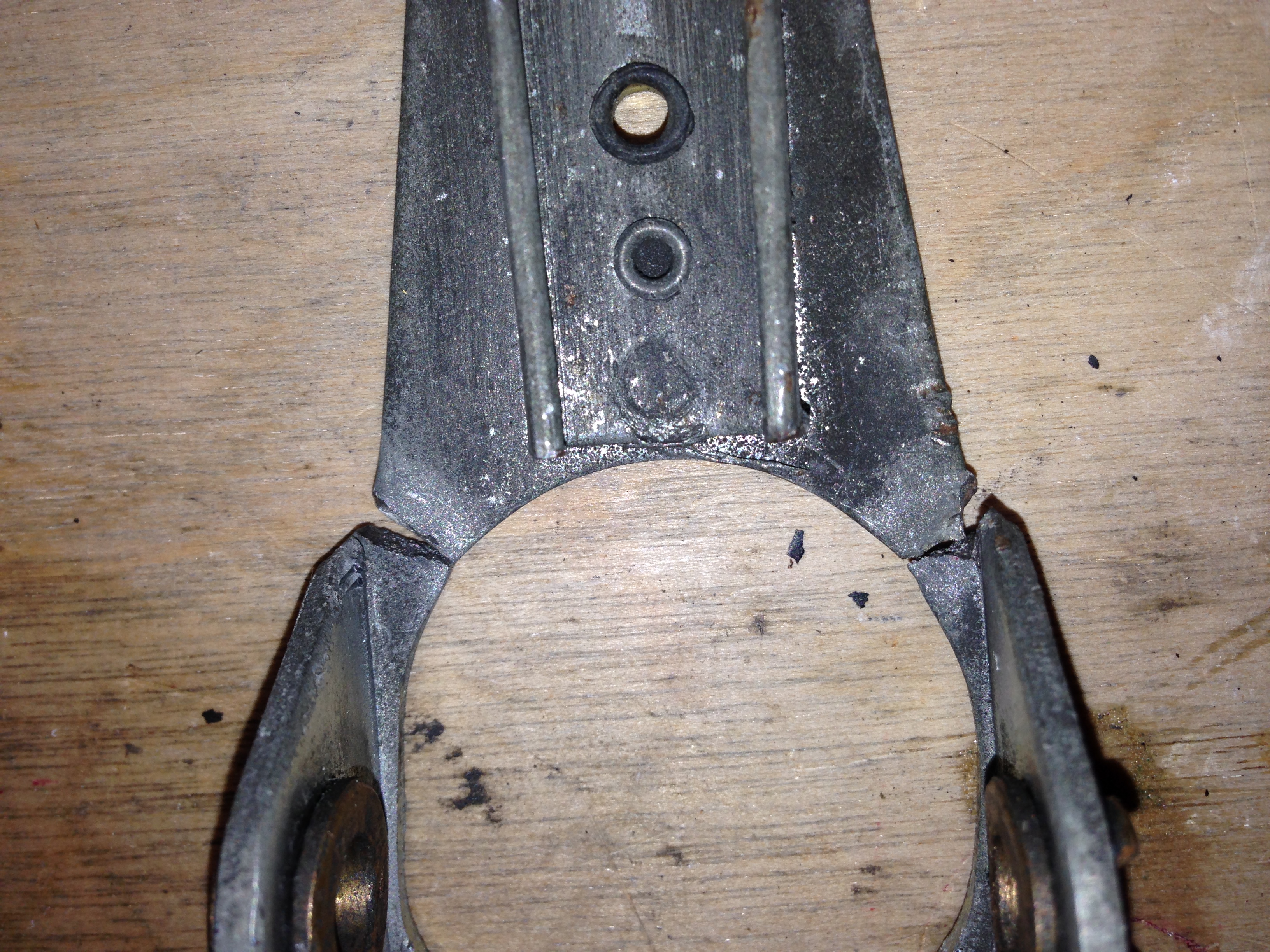
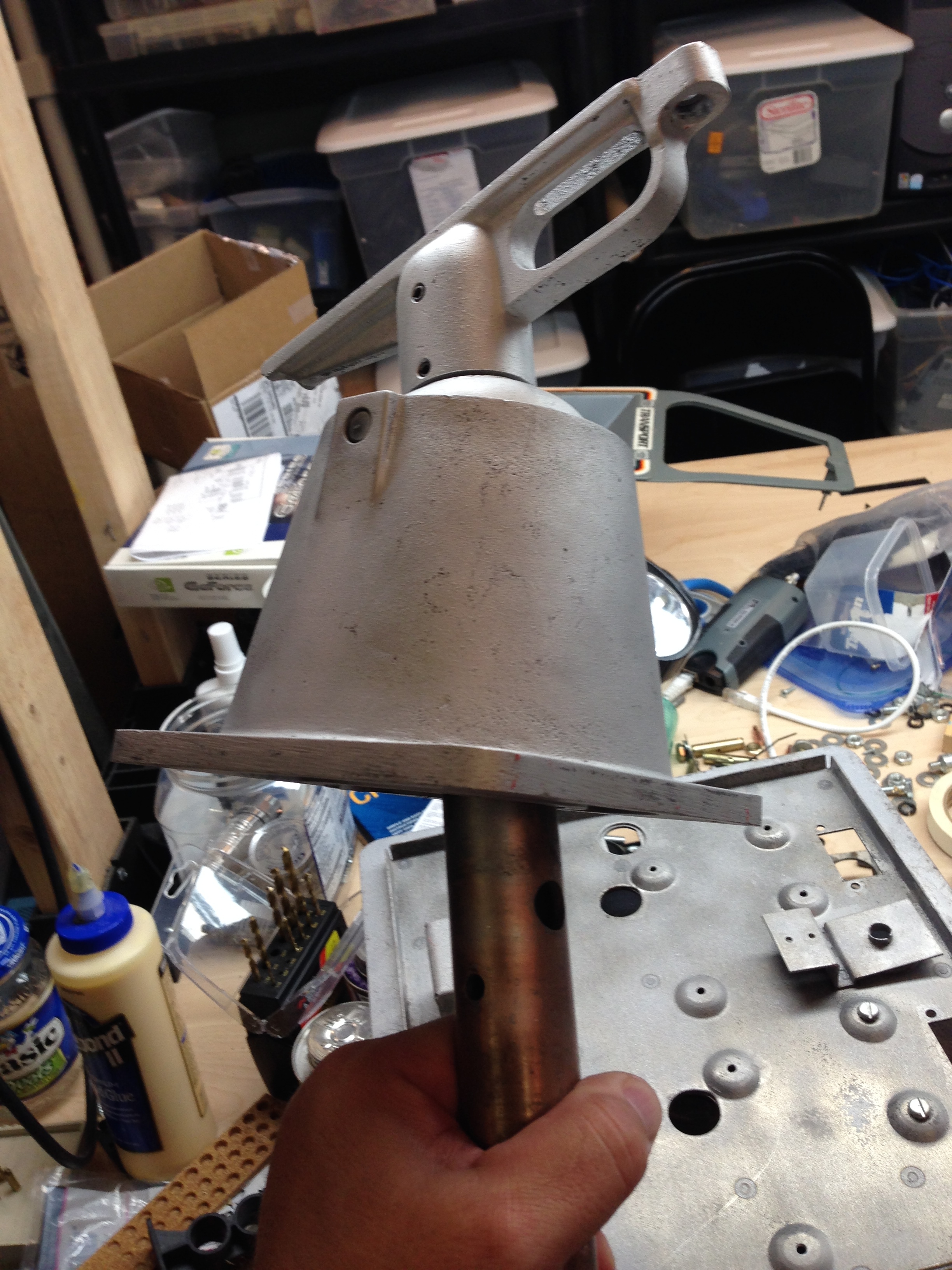
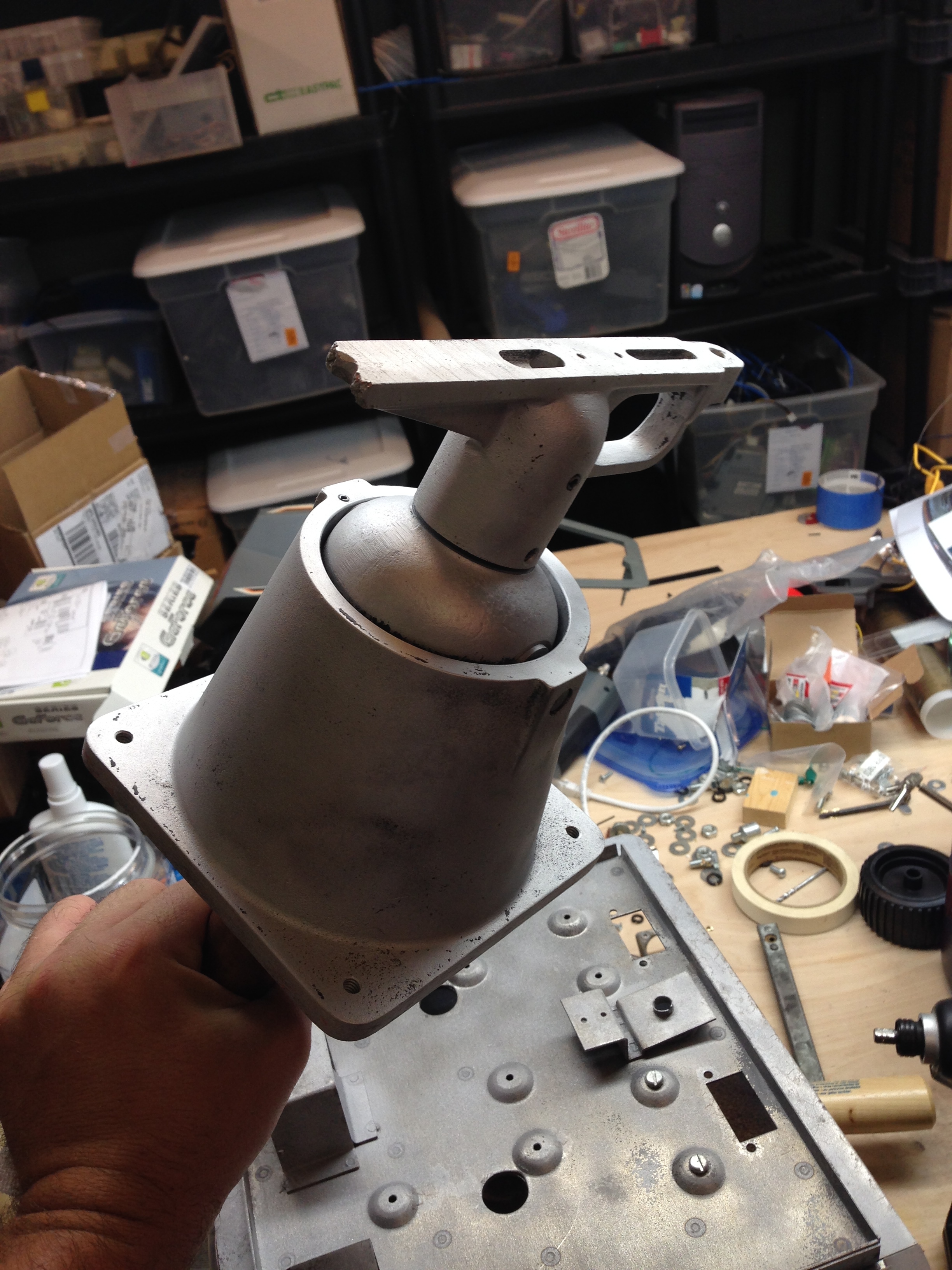
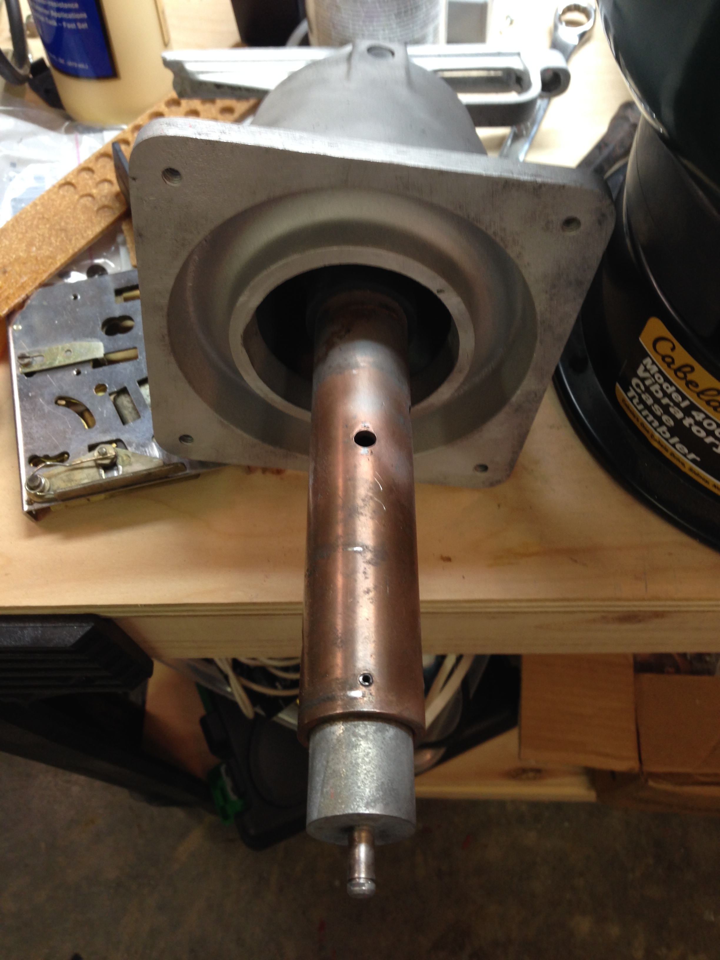
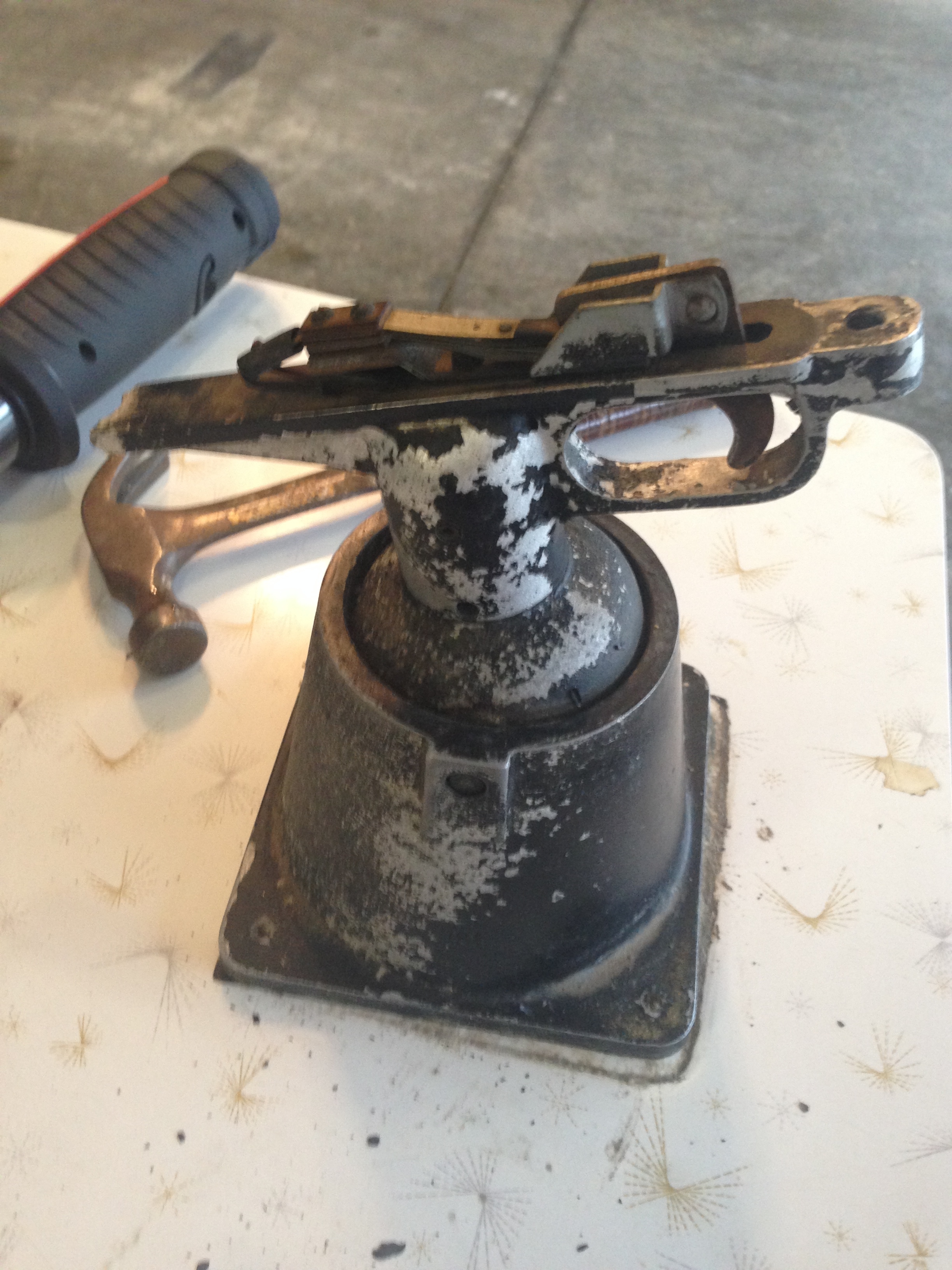
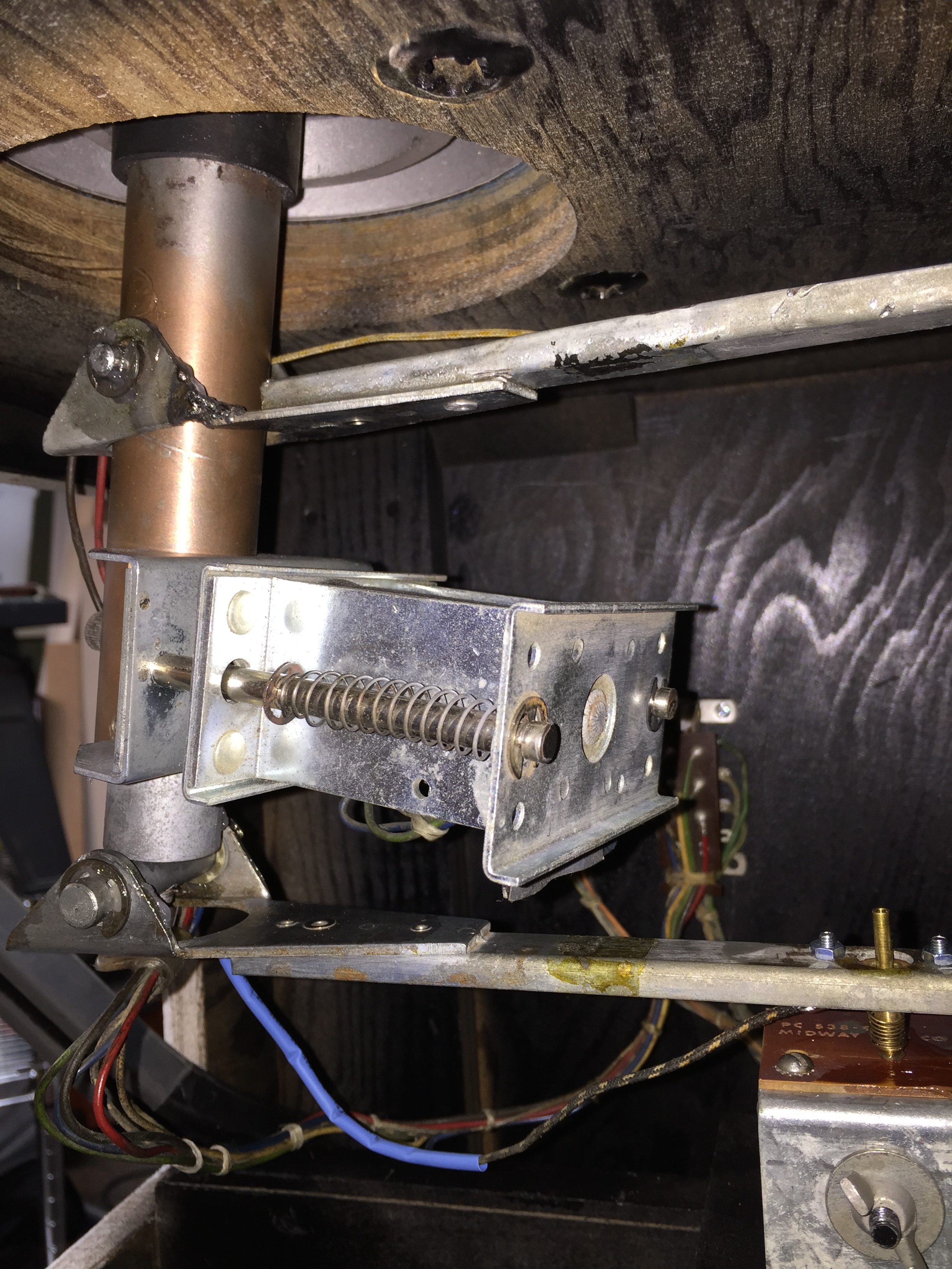
The gun assembly is going to need some work. Here’s the gun base before removal. There are four bolts that unscrew from the bottom. They screw into the gun base. The next picture is of the good bracket. This is the bracket that registers vertical movement. It looks identical to the broken bracket below except that it has a mounting holes that would allow it to be used as either the bottom or top arm, whereas the broken arm below only has a mounting hole for the contact to allow it to be used for the bottom arm.

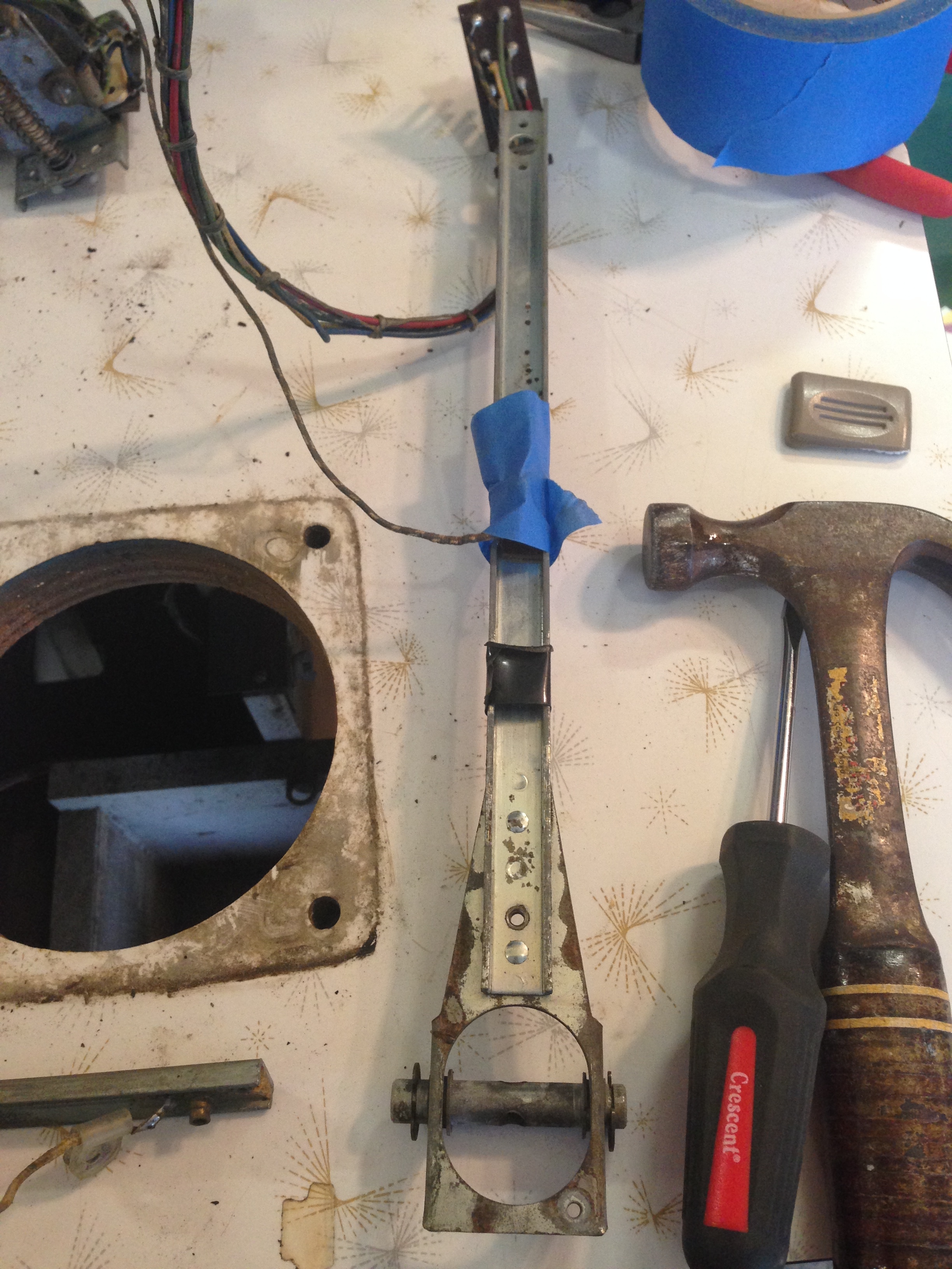
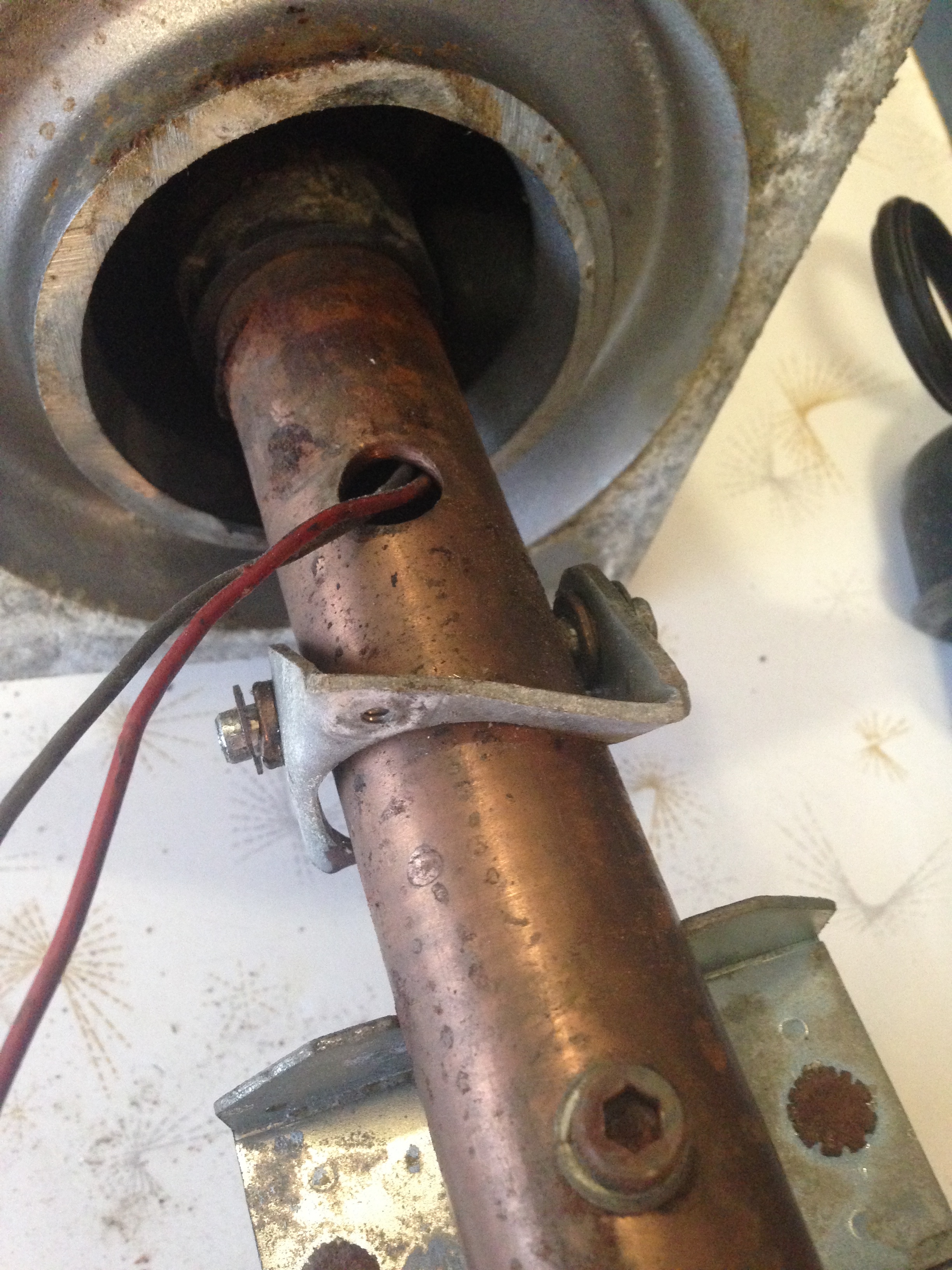
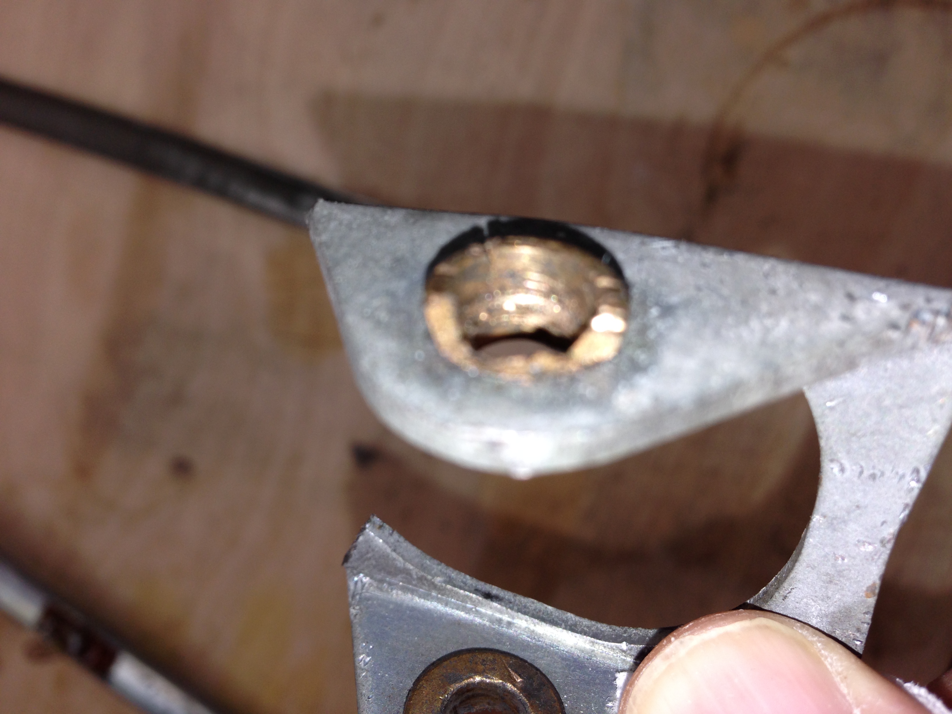
On the middle of the rod coming out of the gun assembly below you can see what’s left of the broken bracket attached to the rod still. I had to hammer the pin out of the rod to release the broken bracket.
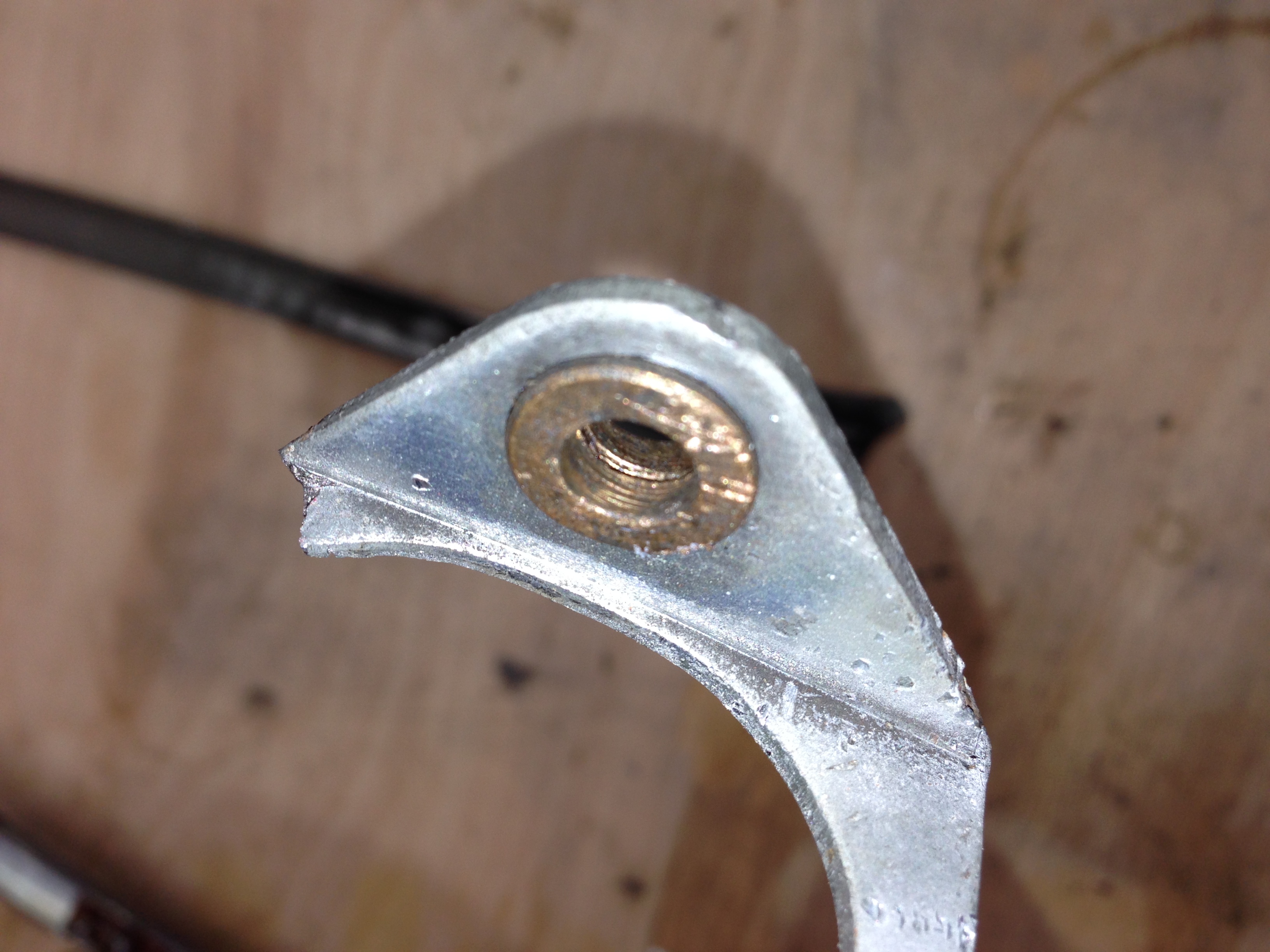
These two pictures show how bent the bracket is. Man, someone had a field day with this thing. This is not weak metal, it’s actually pretty durable.
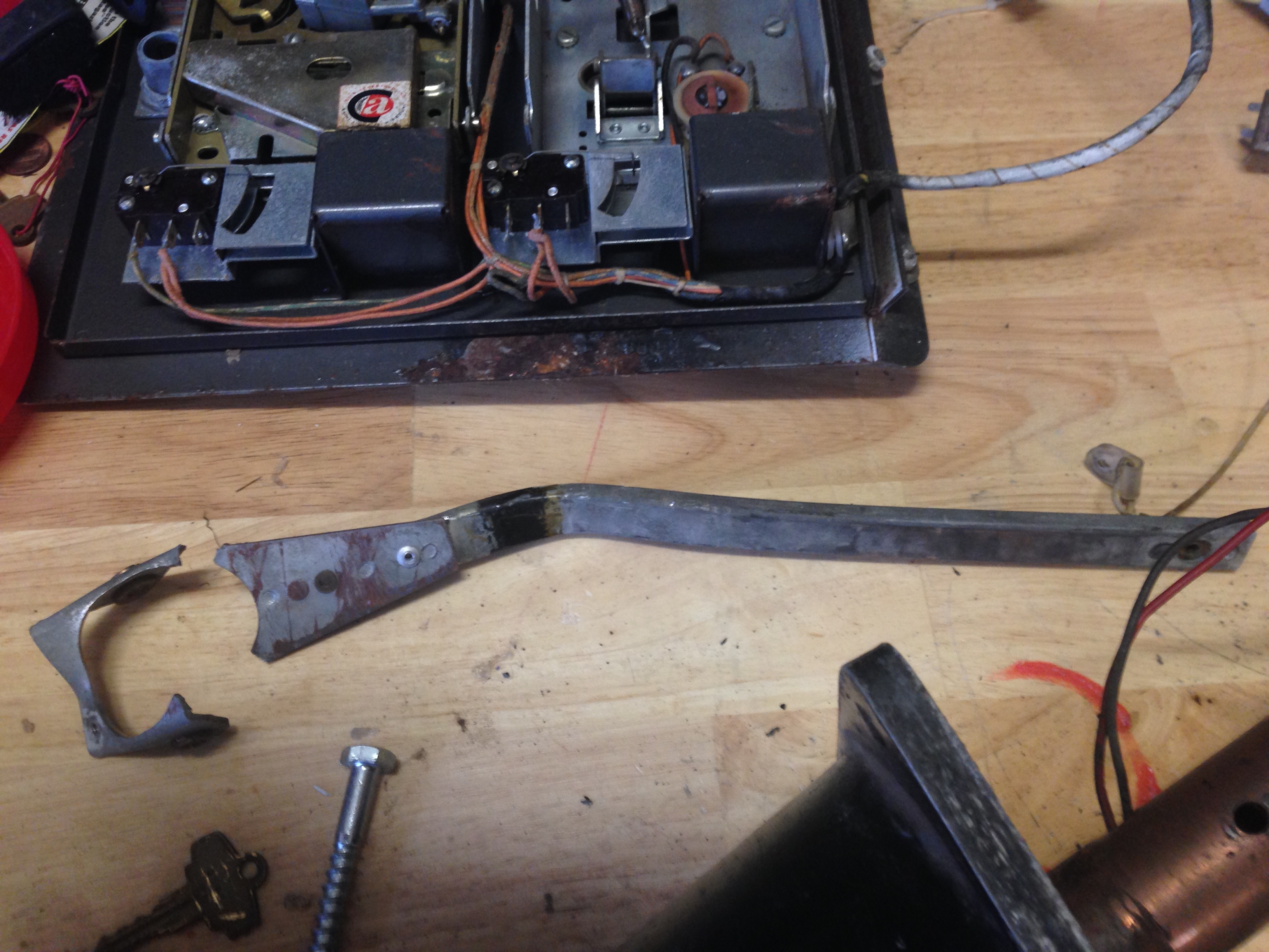
Besides sandblasting and repainting, I have to fix this bracket, and reproduce or replace the pin and spring contact. Looks like I’ll get a chance to learn how to weld!
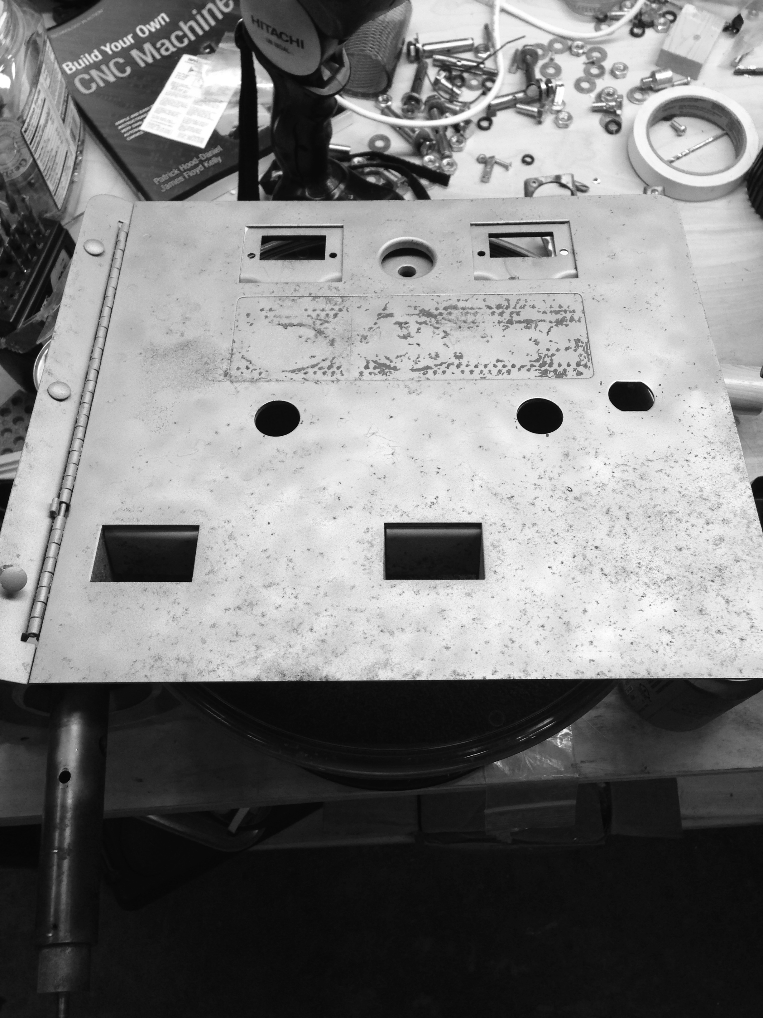
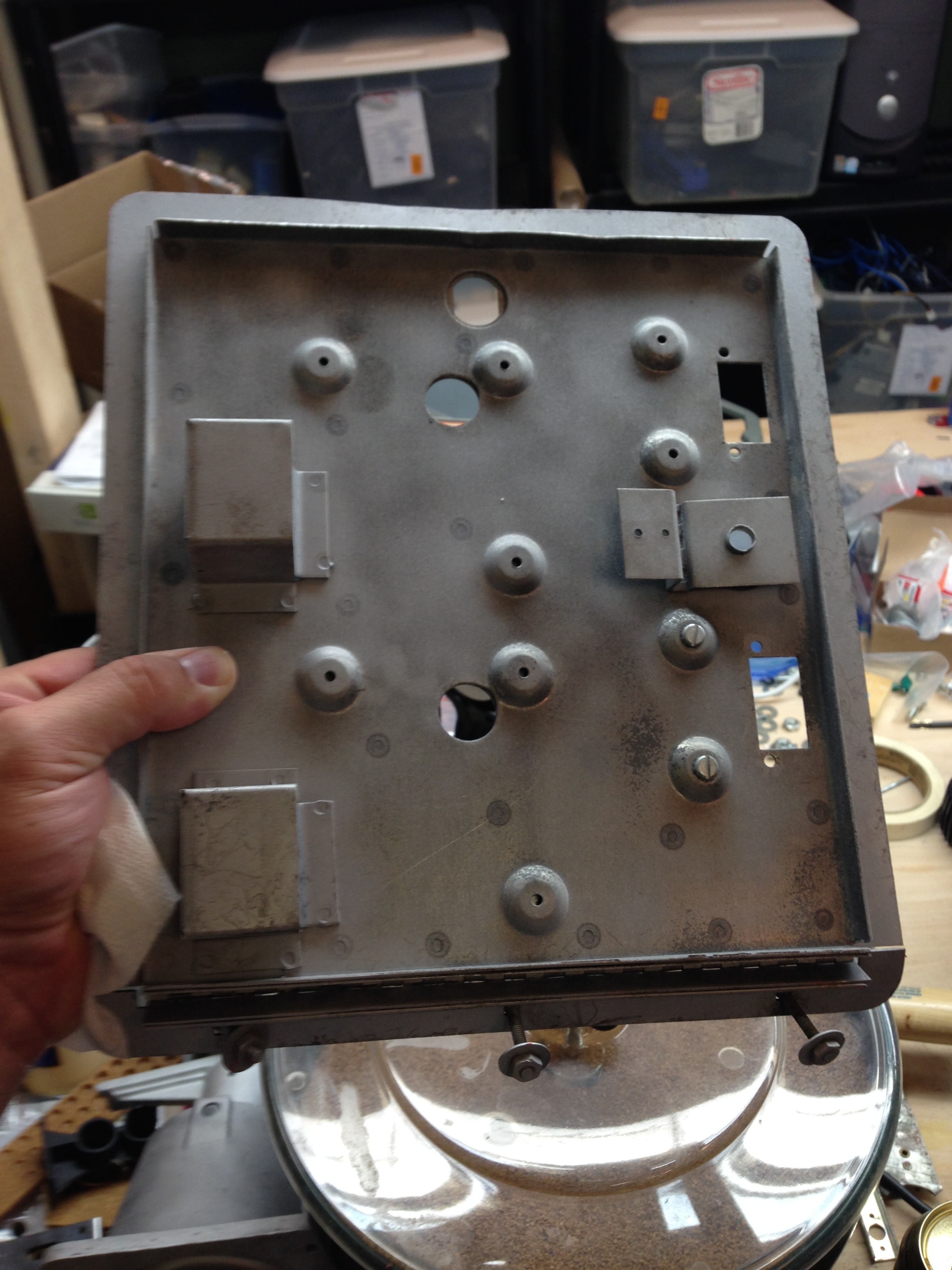
Coin Door
I’m not sure what’s going on with the coin door yet. If you look at the third picture below, you can see there is a chute and coin mech in the left coin slot, but that slot had tape over it. There is no chute or mech on the right side, but there is a coin lockout solenoid (even though it’s slightly mangled). Not sure what’s happened to this thing but it’s been through some trauma.
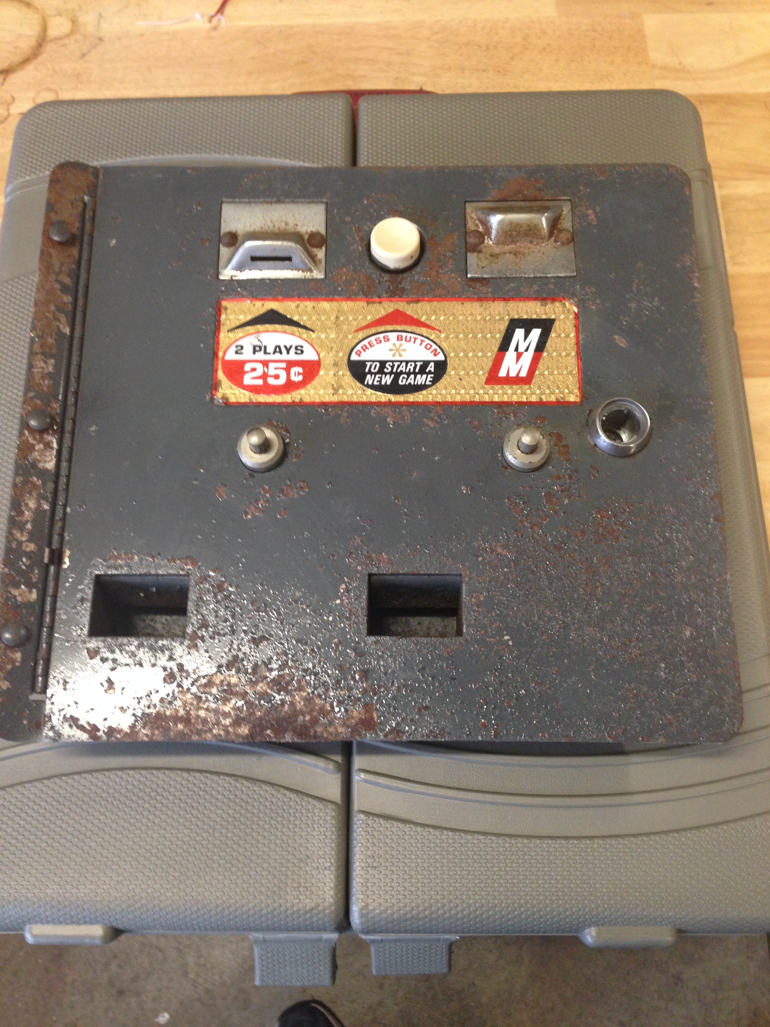
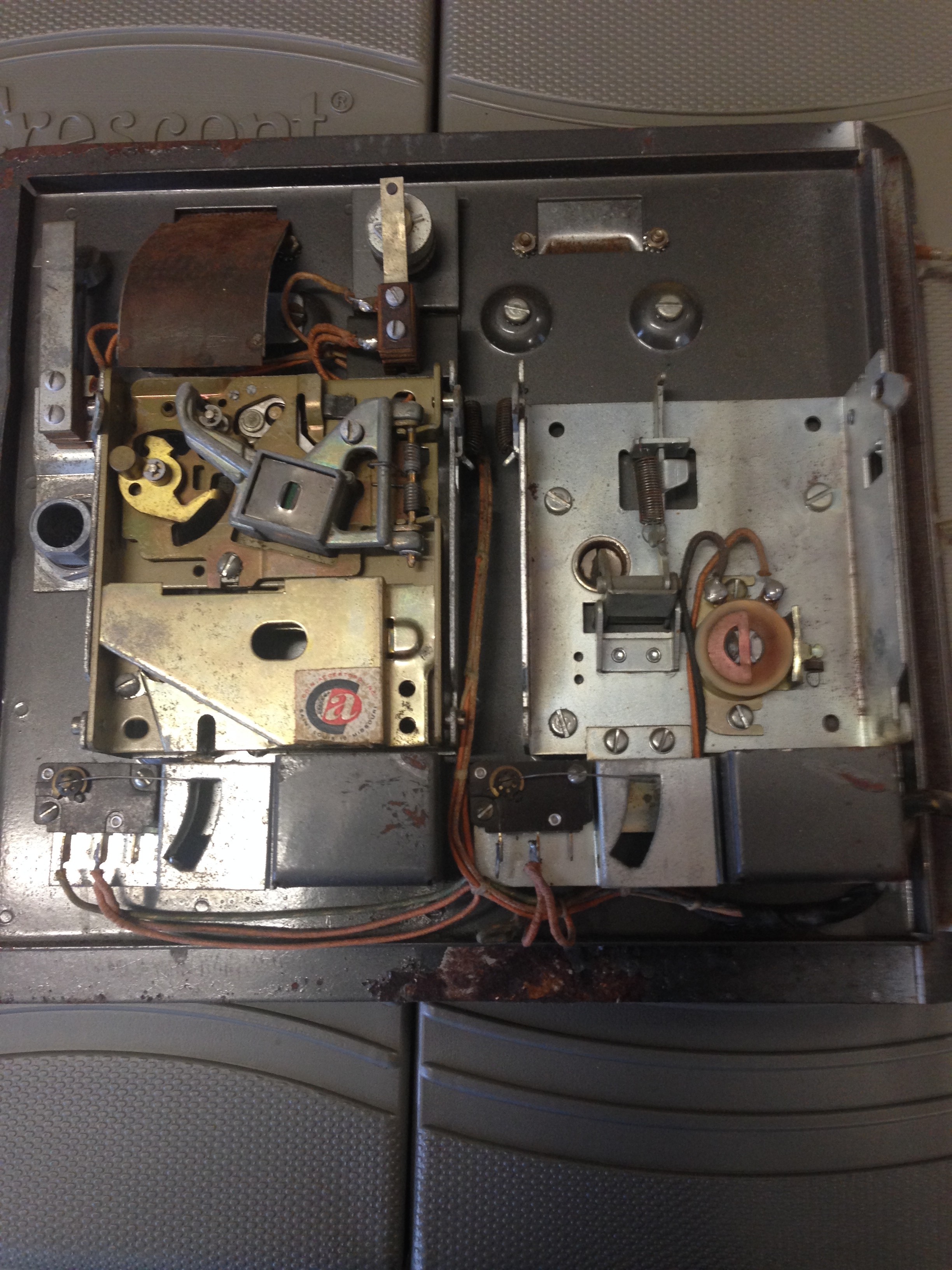
Update: Ok, I figured out what’s going on. I think this was a dime game, with only one coin slot originally. There is only one coin lockout coil in the machine, and I can’t see that it ever had two, so I think maybe someone converted this to 25 cents. I’m not sure why it has some of the hardware for both coin slots, but it doesn’t have all of it, so maybe that’s just what it came with? Anyway, I think I’m going to restore it to 3 plays for 25 cents, 1 play for 10 cents.
Cardboard Targets and Background
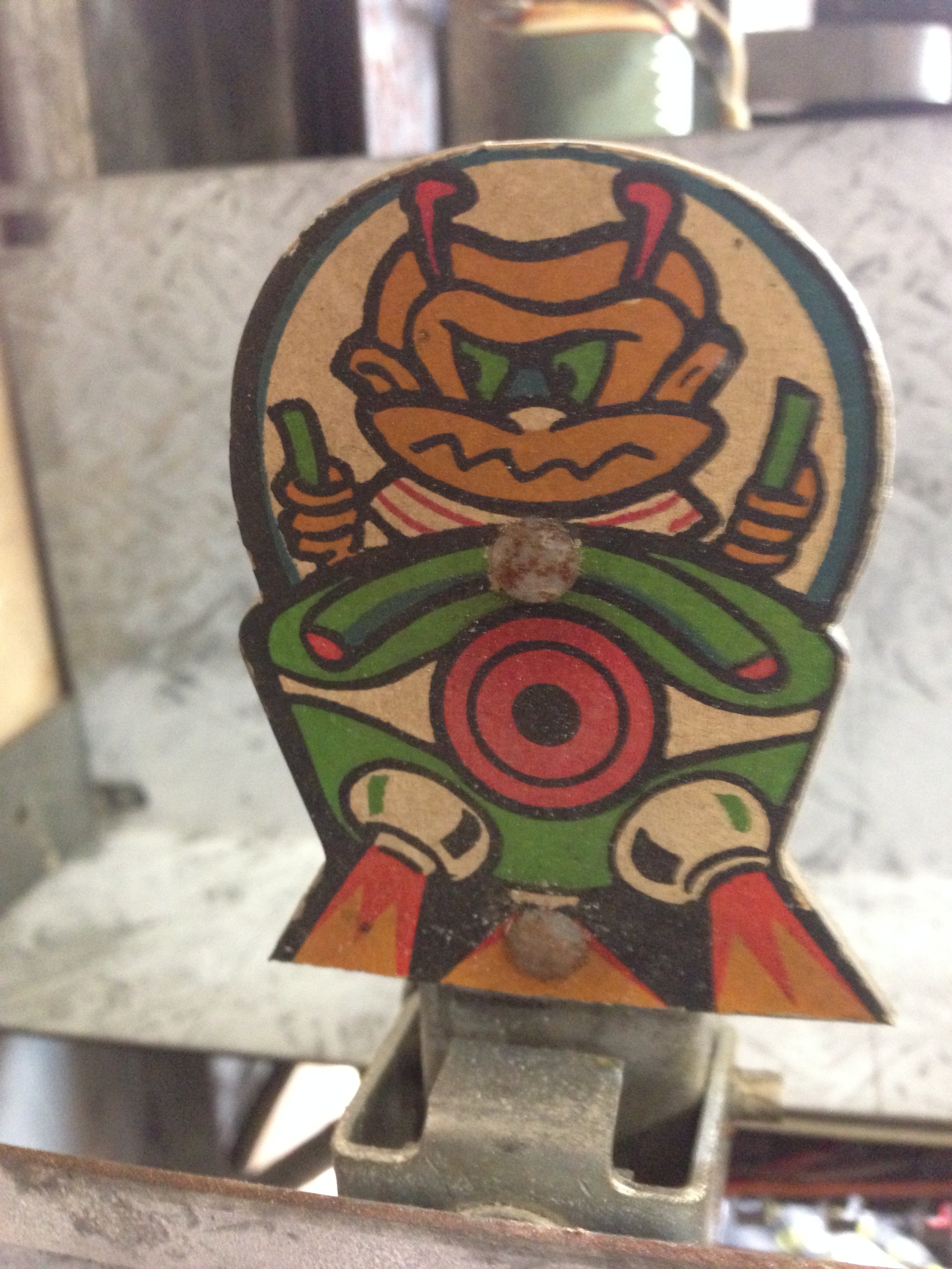
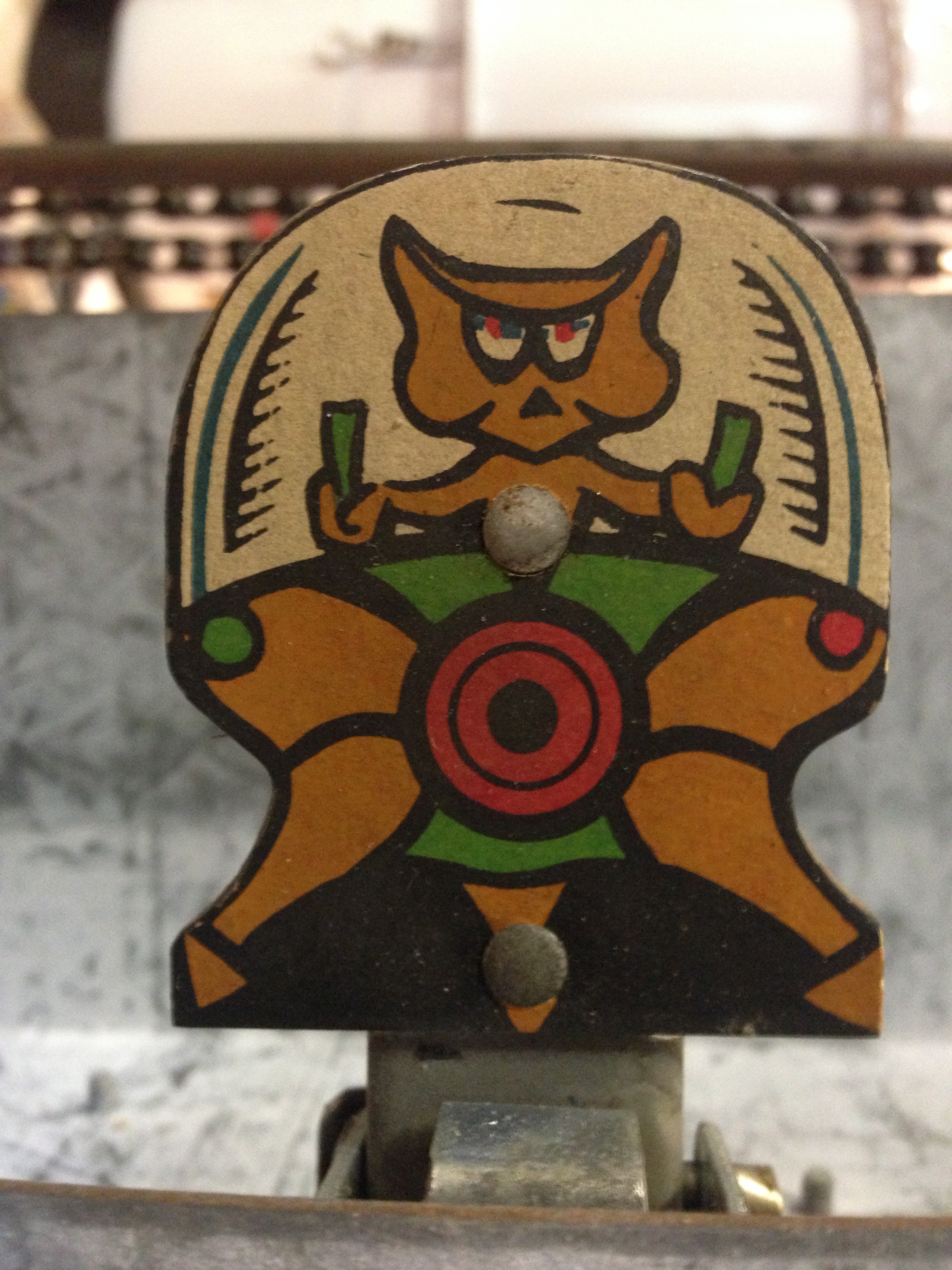
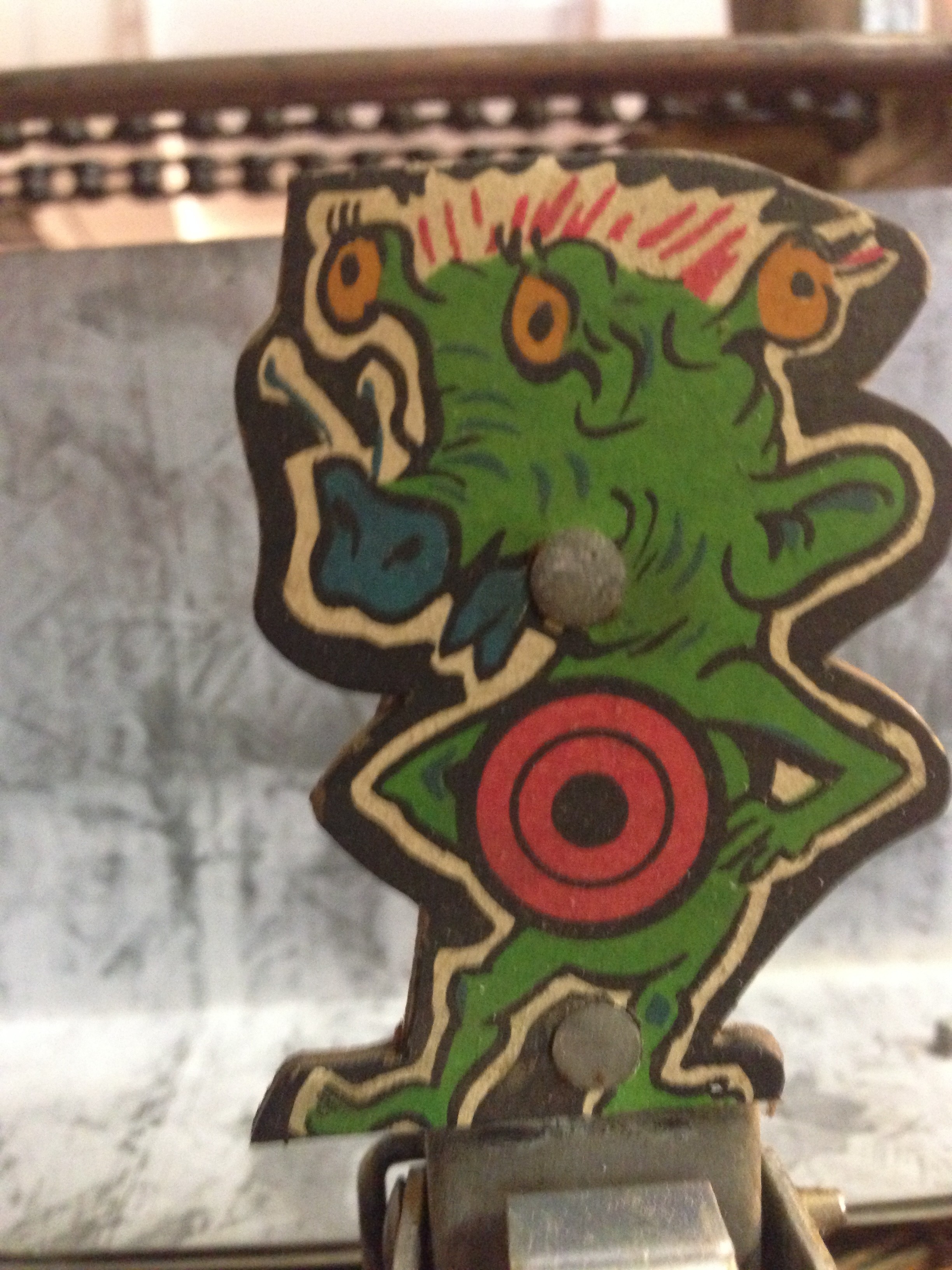
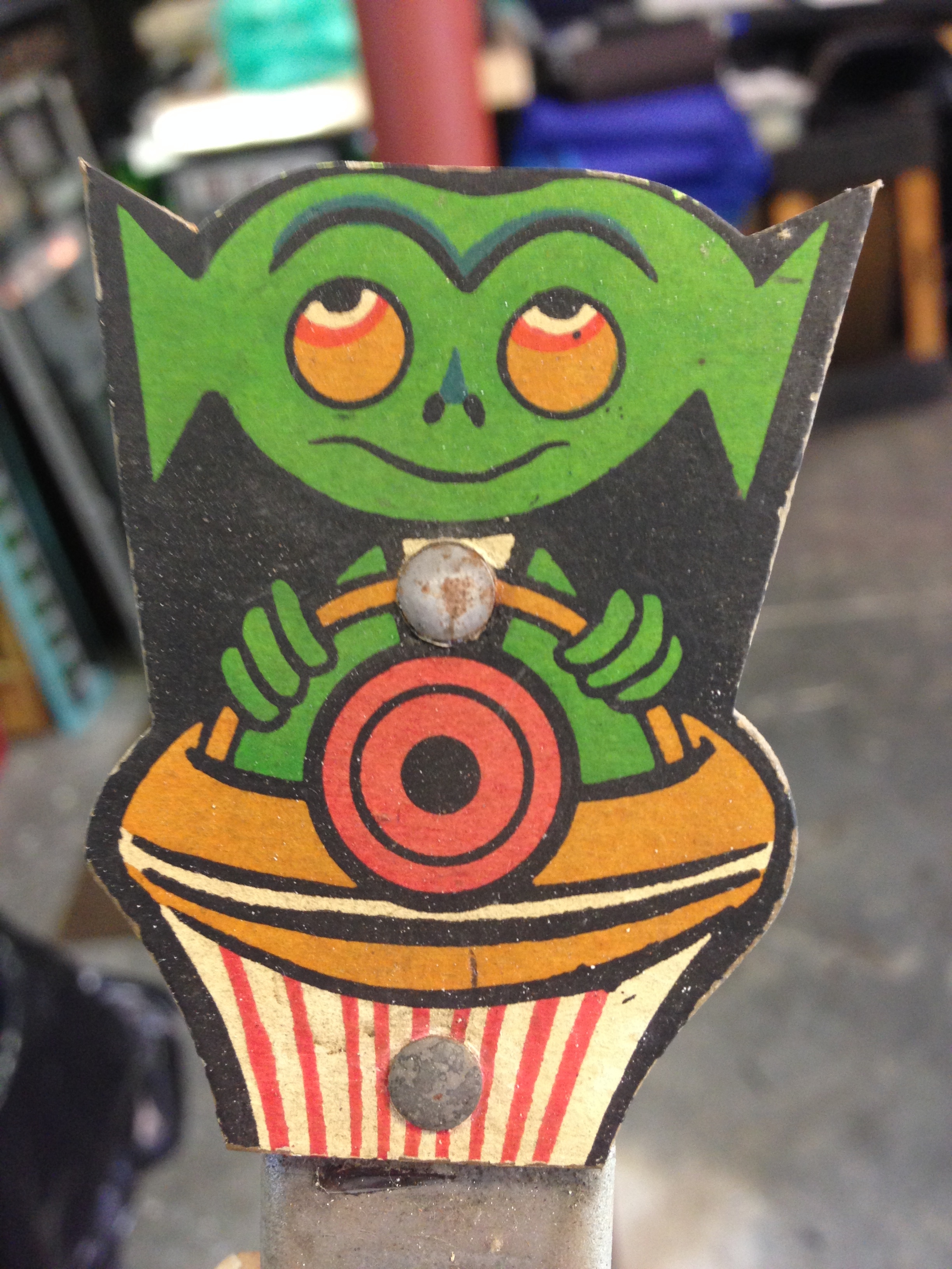
These are not in too bad shape, they are not bent, and not very dirty. I don’t see any creases etc…. I think a careful cleaning with a moist paper towel should brighten them up.
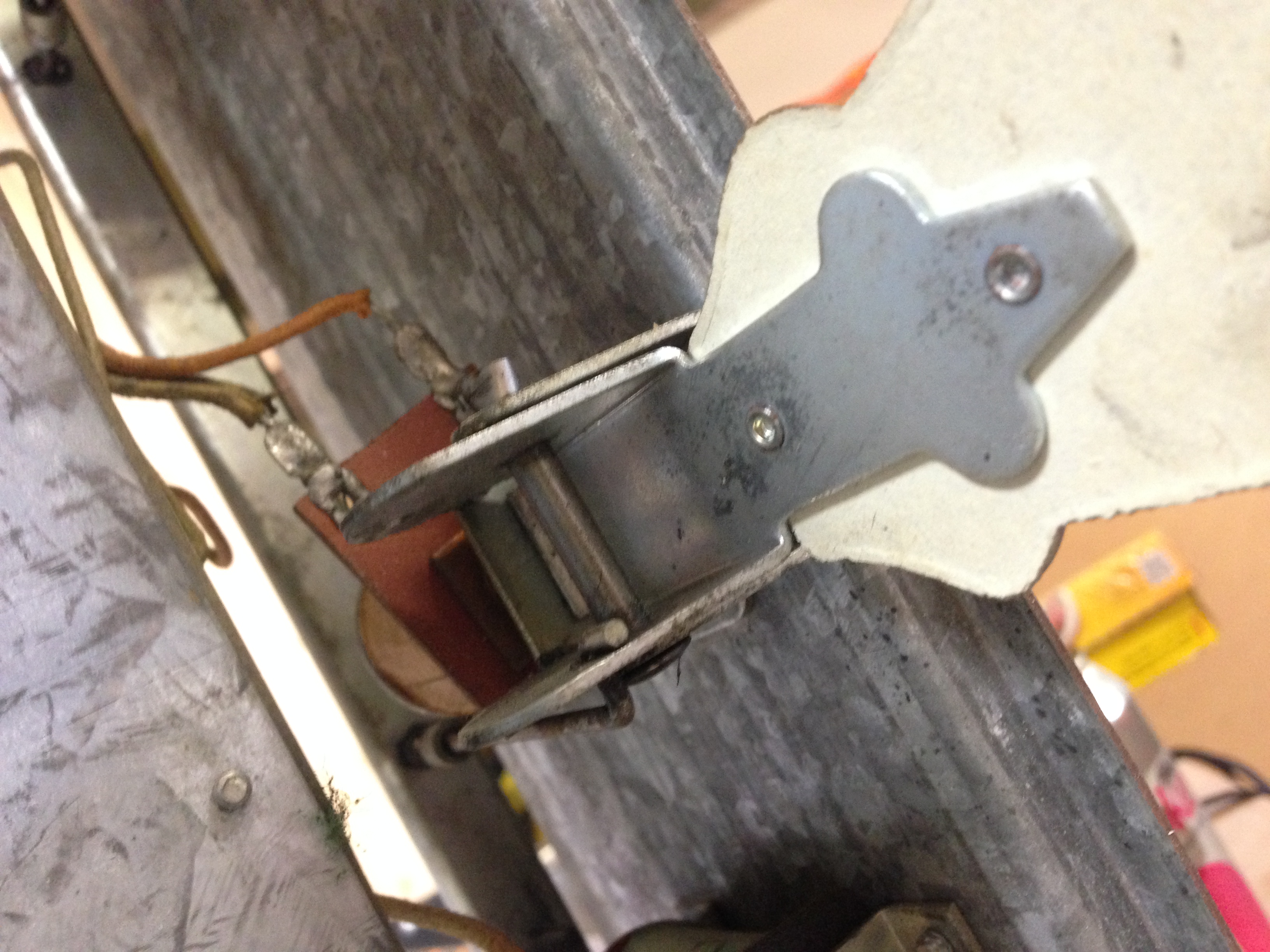
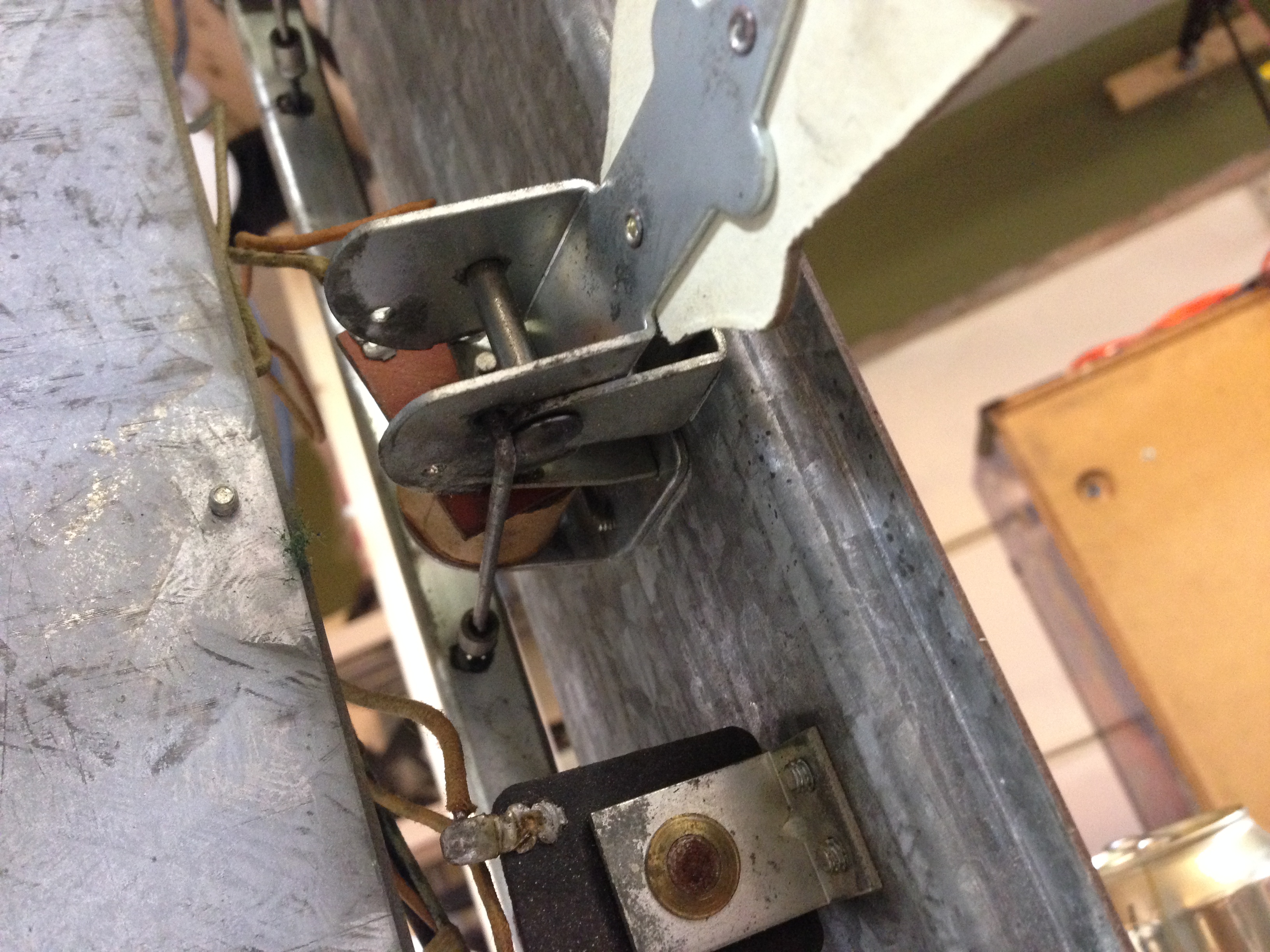
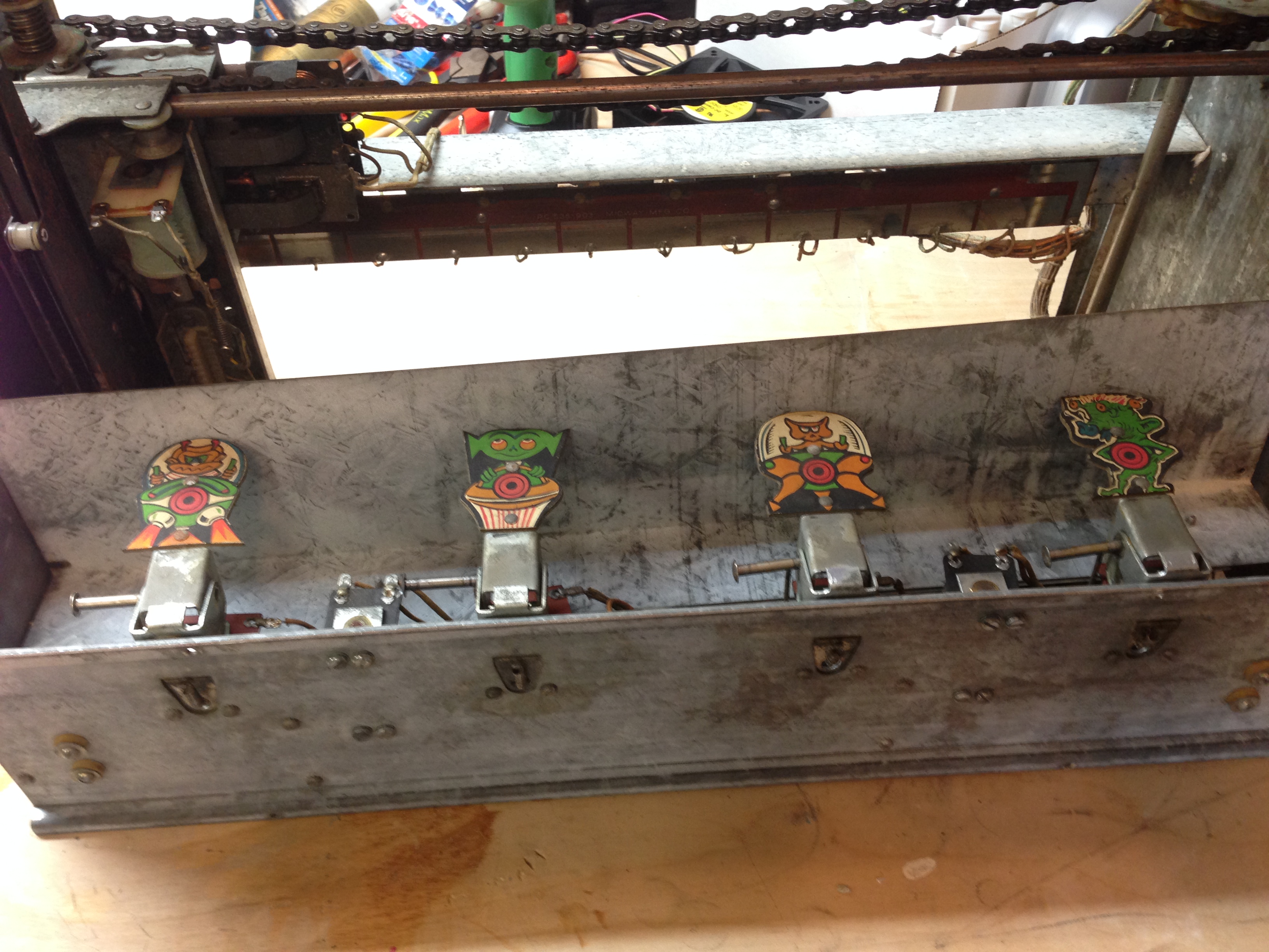
They are held in by a pin that is pinched on the end to hold it in. You have to pinch it back to round, and then slide or tap it out.
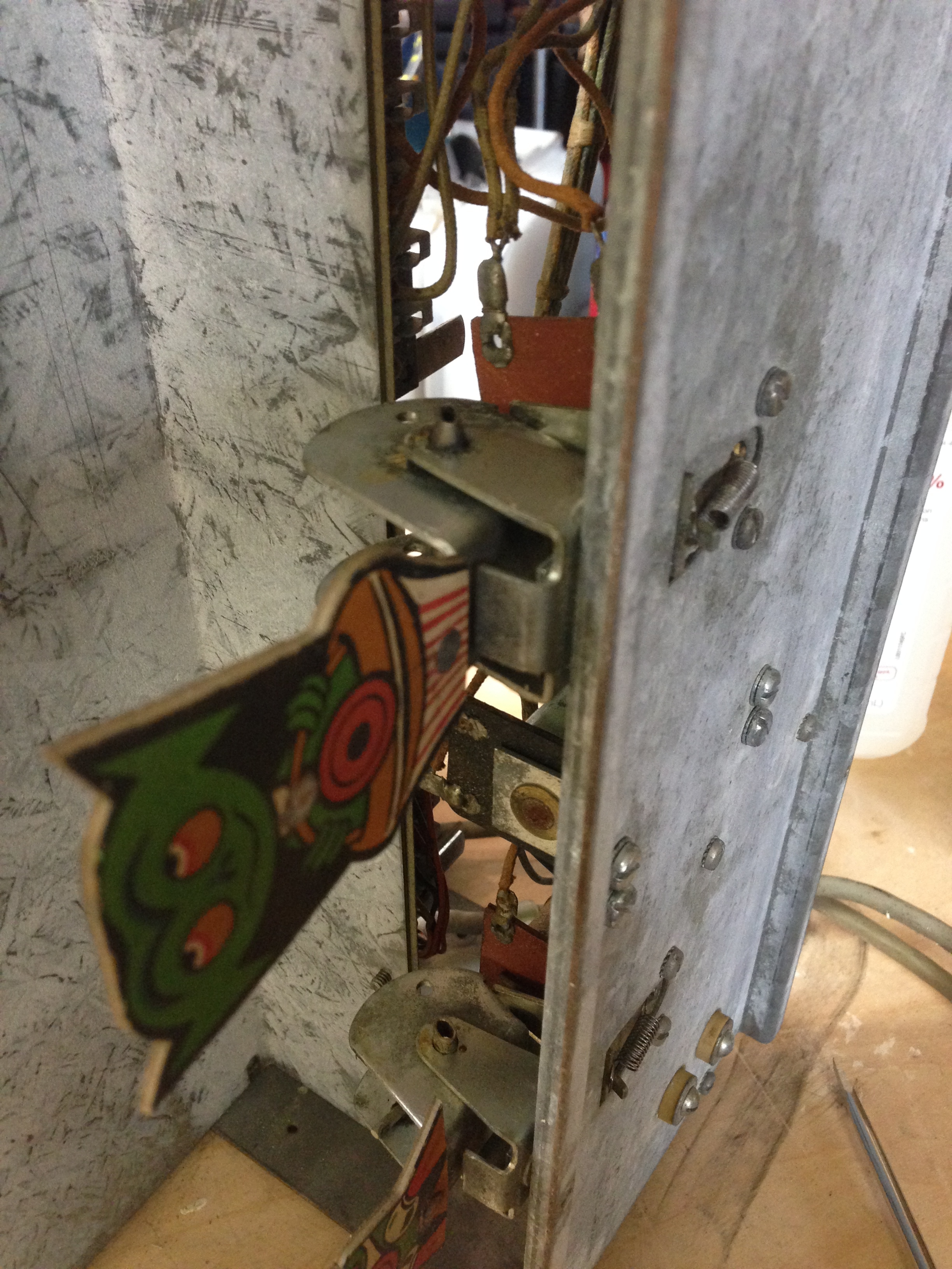
It’s a little hard to see, but here are the two cardboard backgrounds. They are bent, creased, and very, very dirty. Hopefully these will clean up. We’ll have to see…
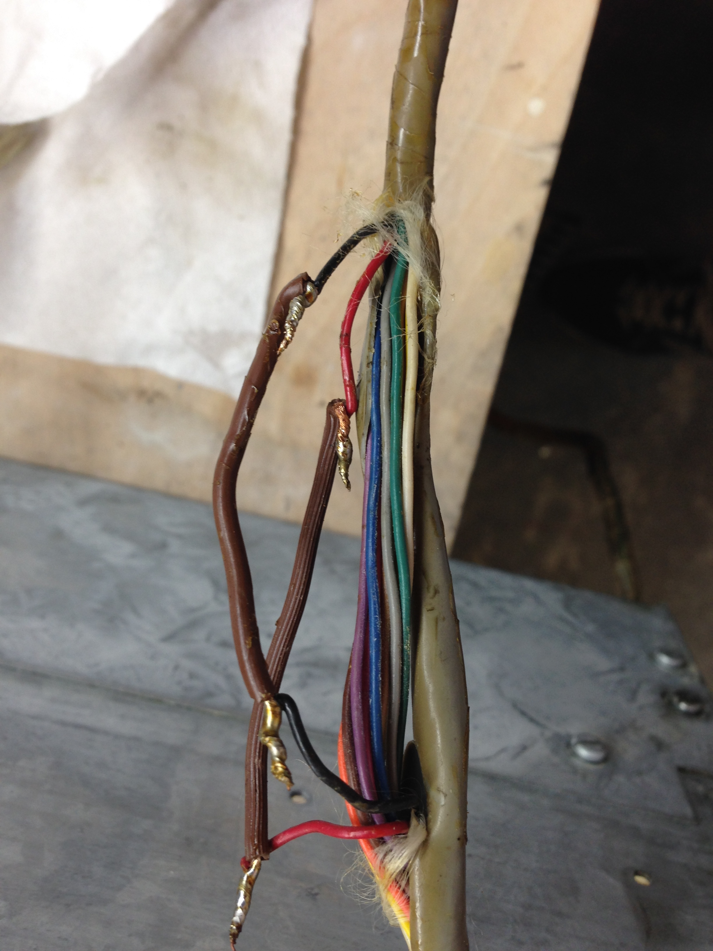
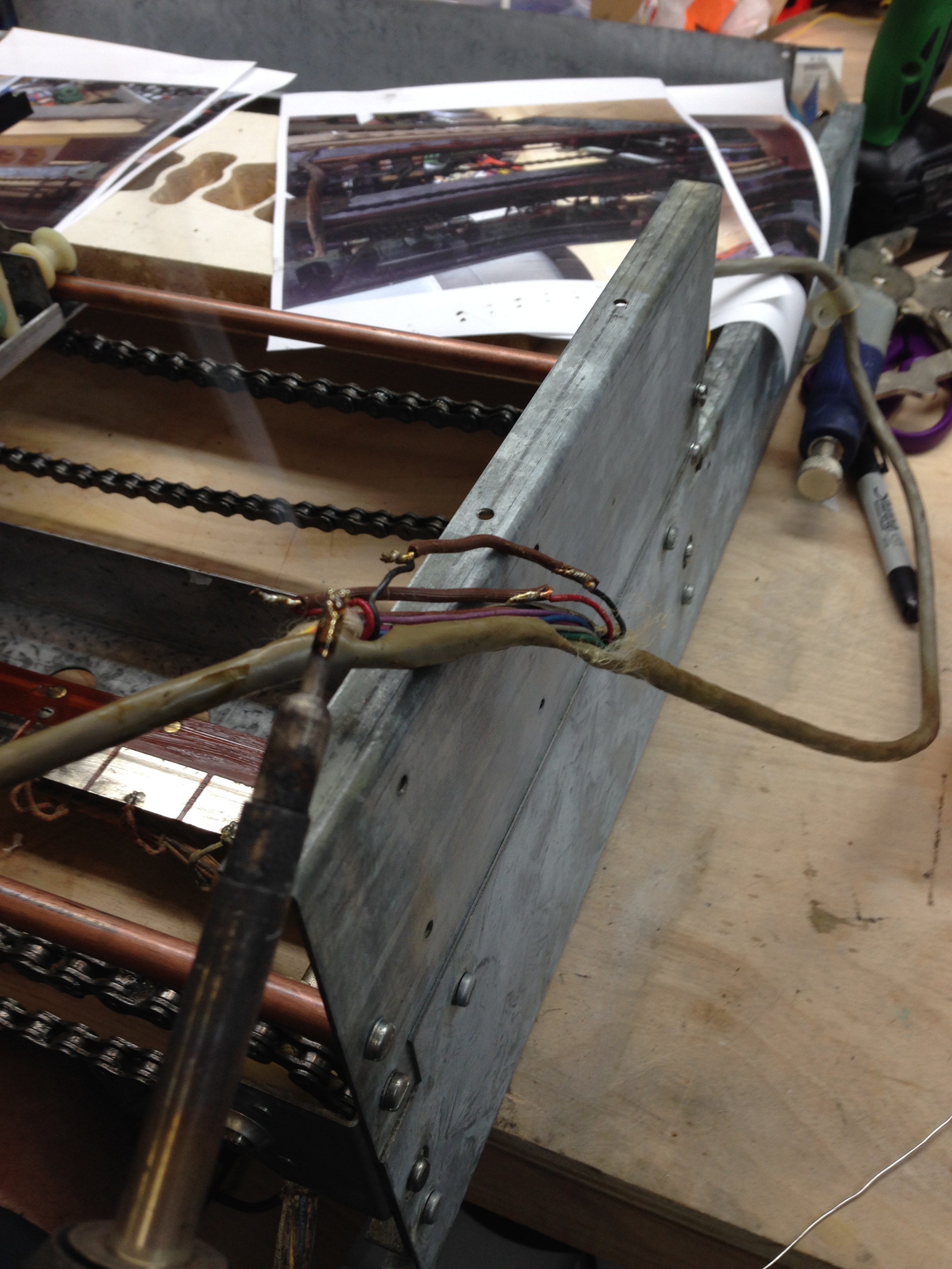
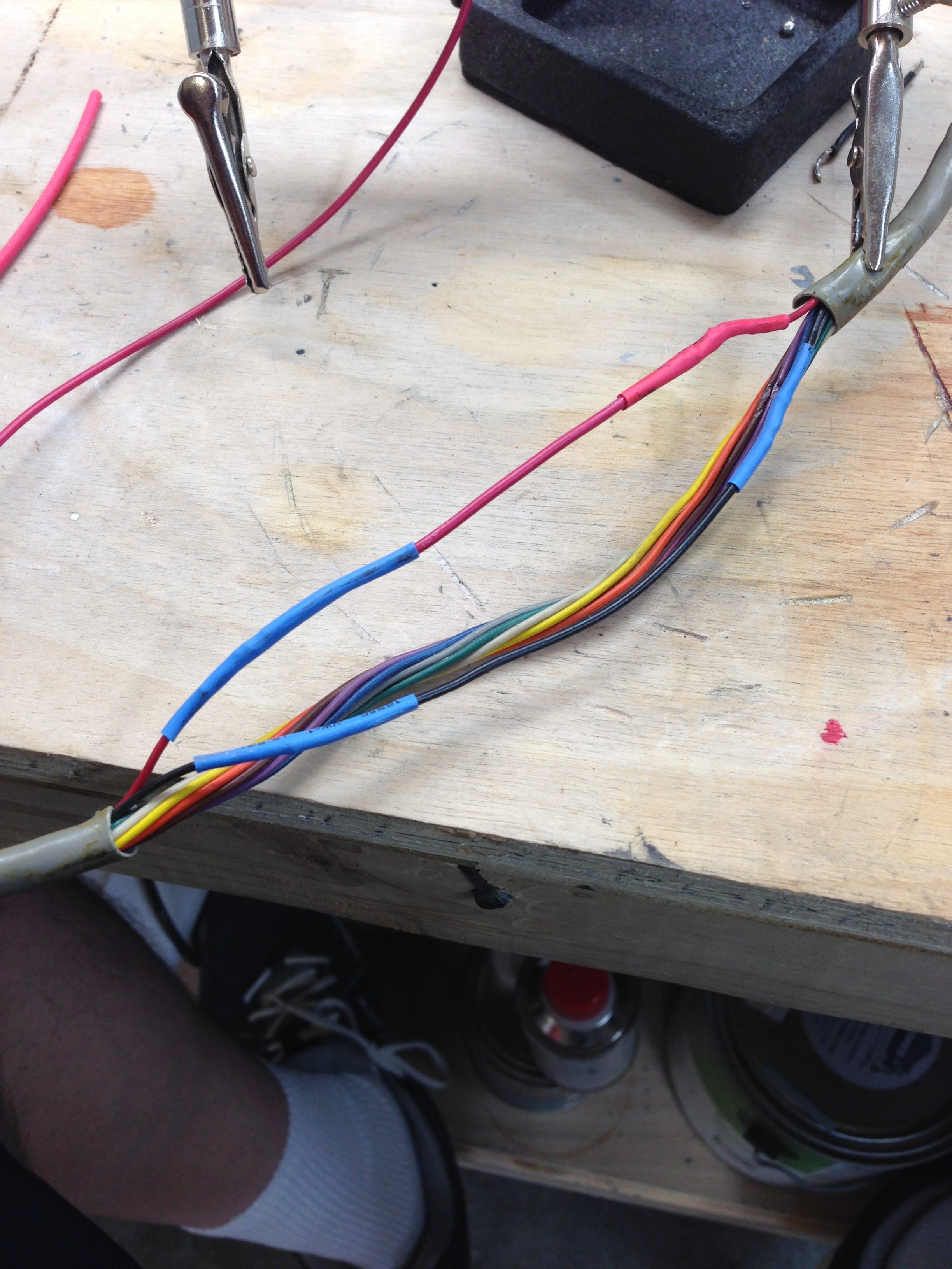
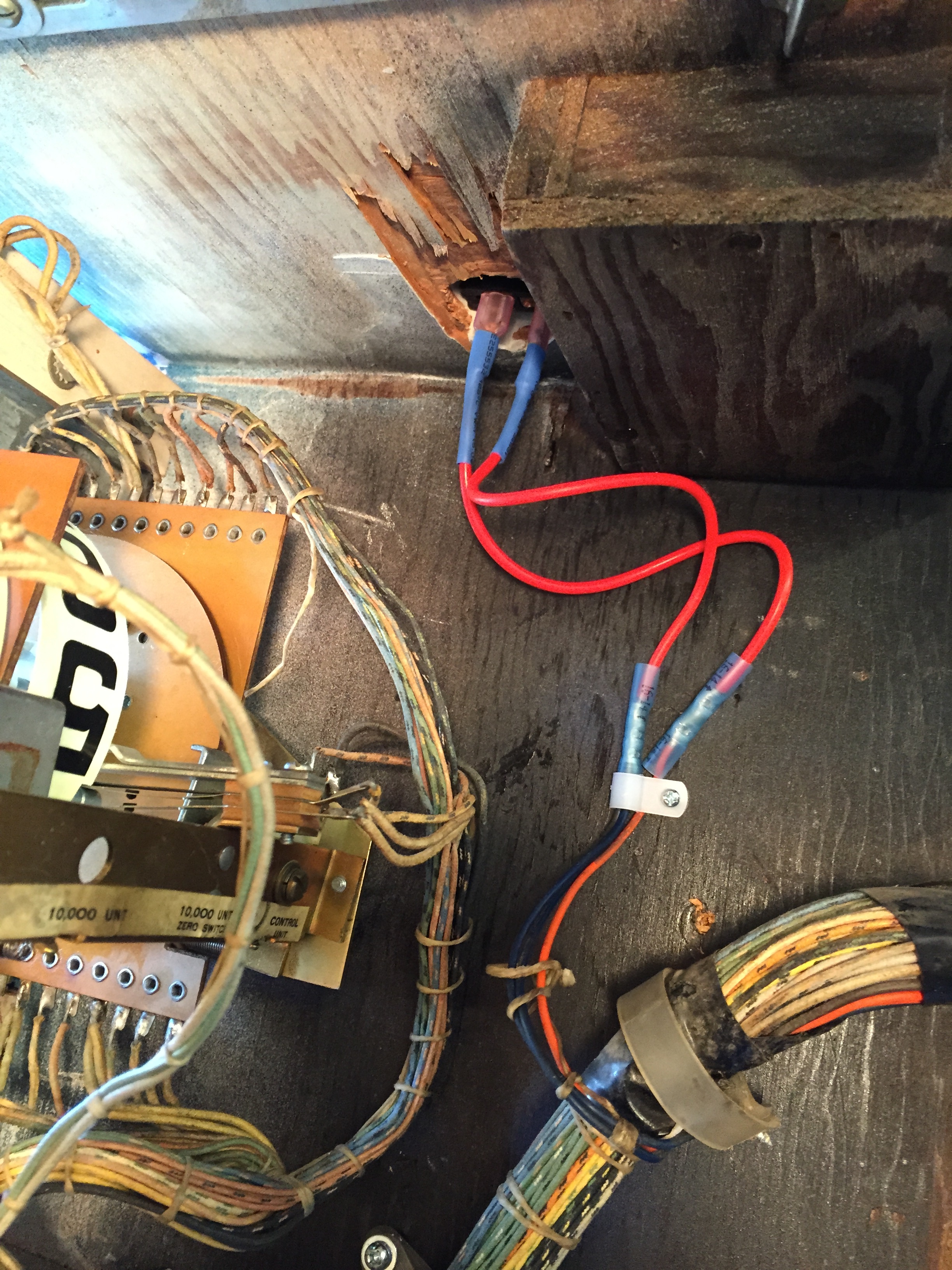
The cable connecting the target unit must have developed a break in 2 of the wires, possibly due to the cable not being routed properly and rubbing on something in the game. These wires were soldered back together with lamp cord and taped with electrical tape. I think I’m going to replace the lamp cord with stranded wire of the proper gauge and use heat shrink tubing to cover it. I won’t be able to use heat shrink on the cable itself without removing the connector, so I’ll probably re-tape once I’ve fixed the wires.
I cleaned, de-rusted, and re-assembled parts of the target unit this week. I cleaned all the old grease off both motors. Some of the assemblies had quite a bit of rust on them, whereas others just needed a cleaning and tumbling. Here’s some before and after shots.
Before
After
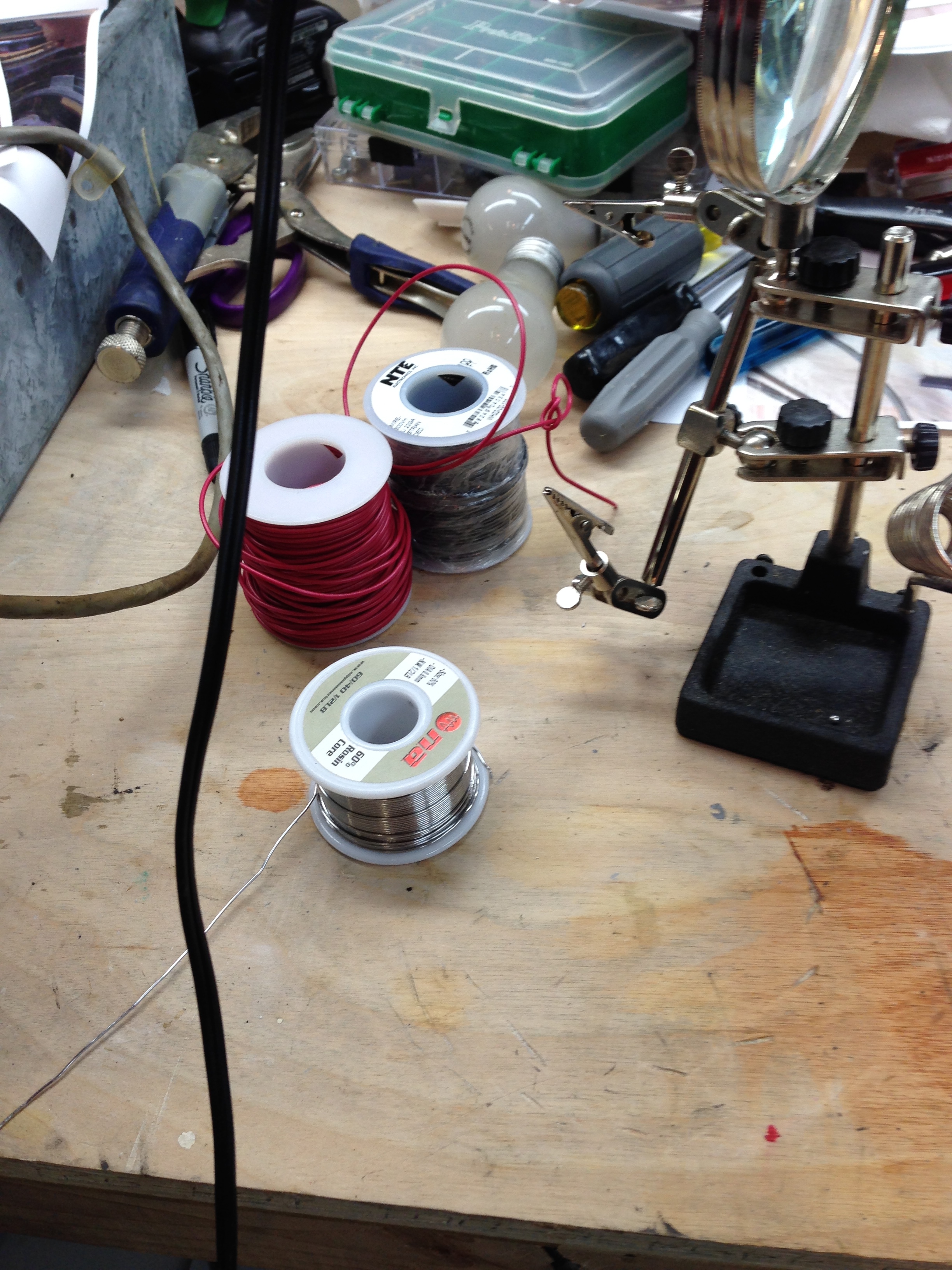
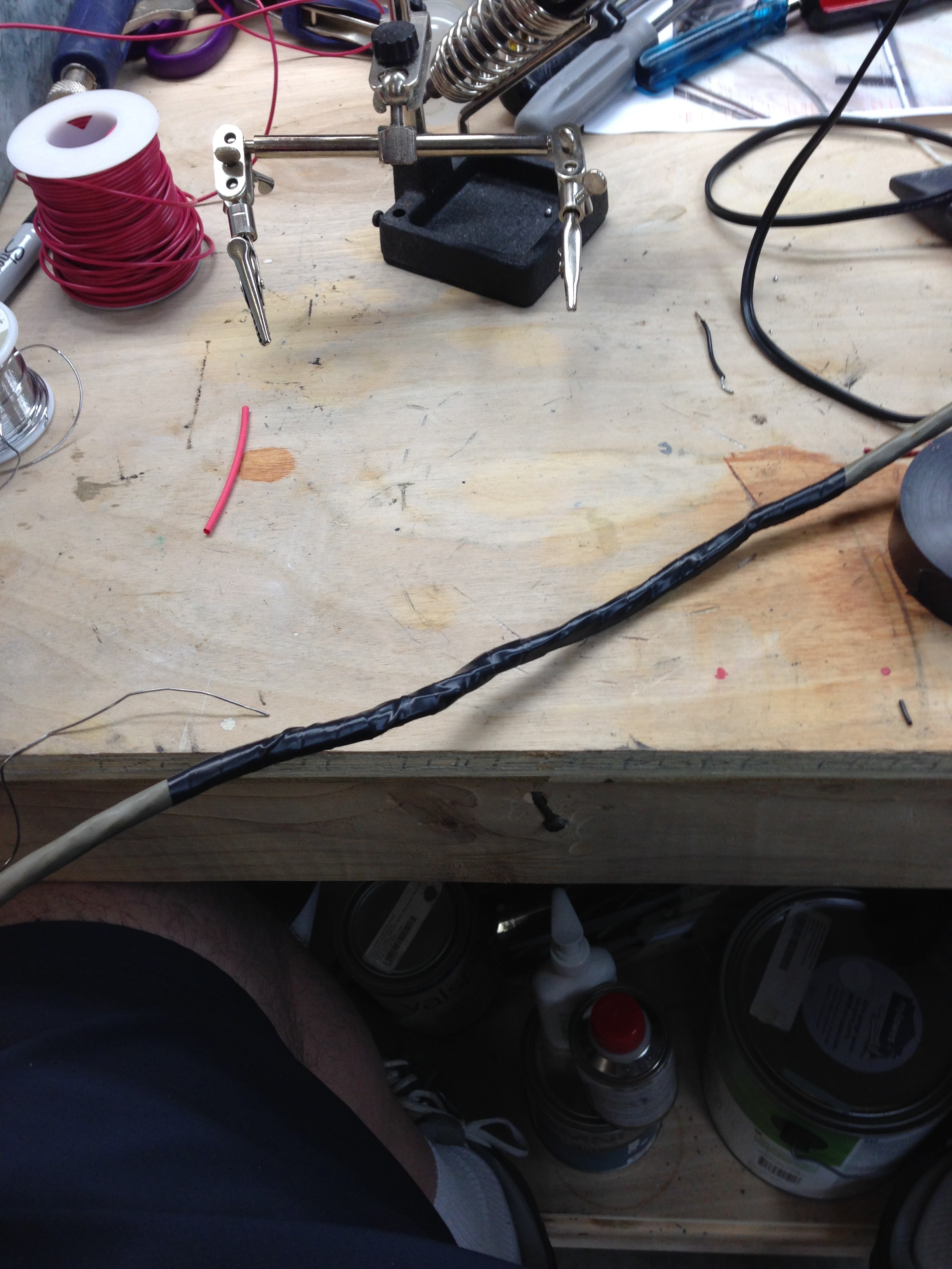
I repaired the cable this evening. I cut red and black wires to proper length, and soldered them with shrink wrap tubing insulation and then taped the whole thing with electrical tape. Some of this work was just “to do it right” and partly to ensure that the movement of the cable back and forth wouldn’t stress the wires in unusual ways.
It’s getting close to time to try my hand at welding. I was able to bend the broken bracket back into shape (almost). I think it will be good enough if I can get it welded properly… Here’s some before and after pictures.
After:
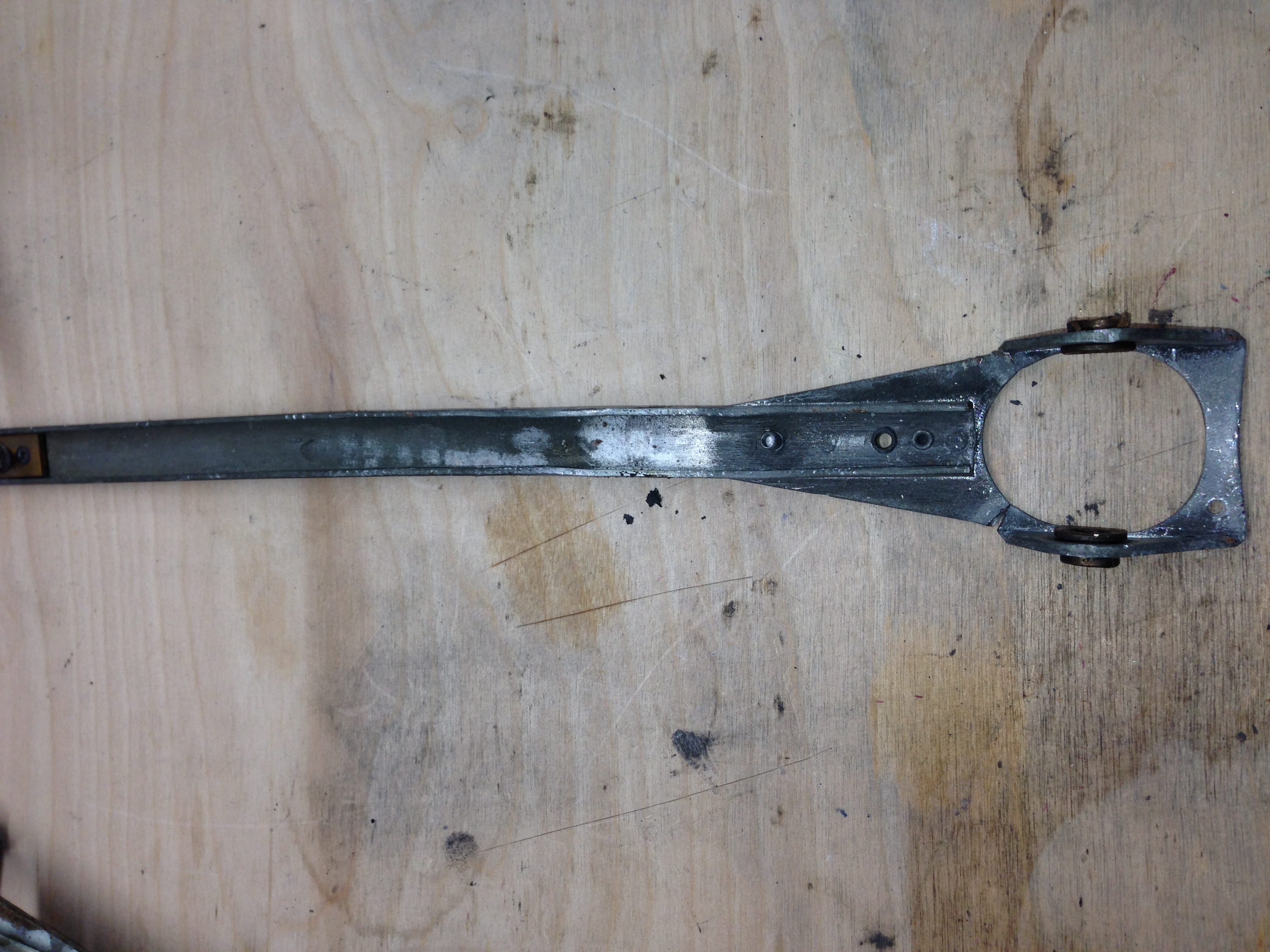
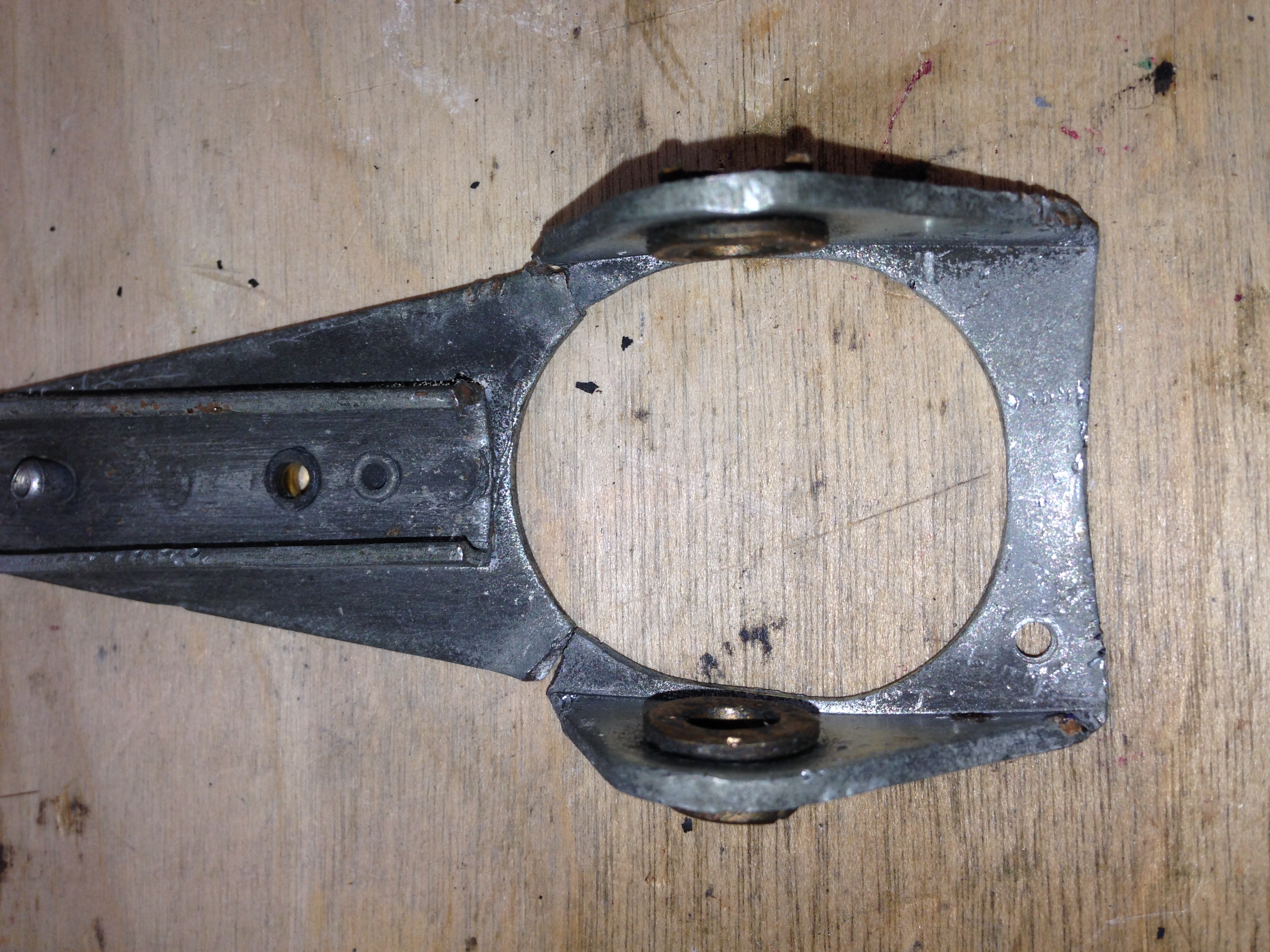
I noticed that the brass bearings on this assembly are starting to break up a little bit. I think this is from clamping this in the vice while bending the piece back into shape. Not sure what I’m going to do about this.
Welding
I finally got around to the welding I needed to do. After watching a number of videos on youtube (and figuring out exactly what kind of welding I should do), I gave it a shot. It’s not the prettiest welding in the world, but it got the job done. Here’s a few pictures of the part, the welder, and the clamps etc… I used.
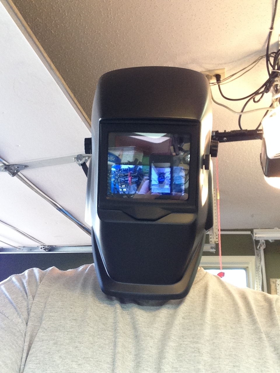
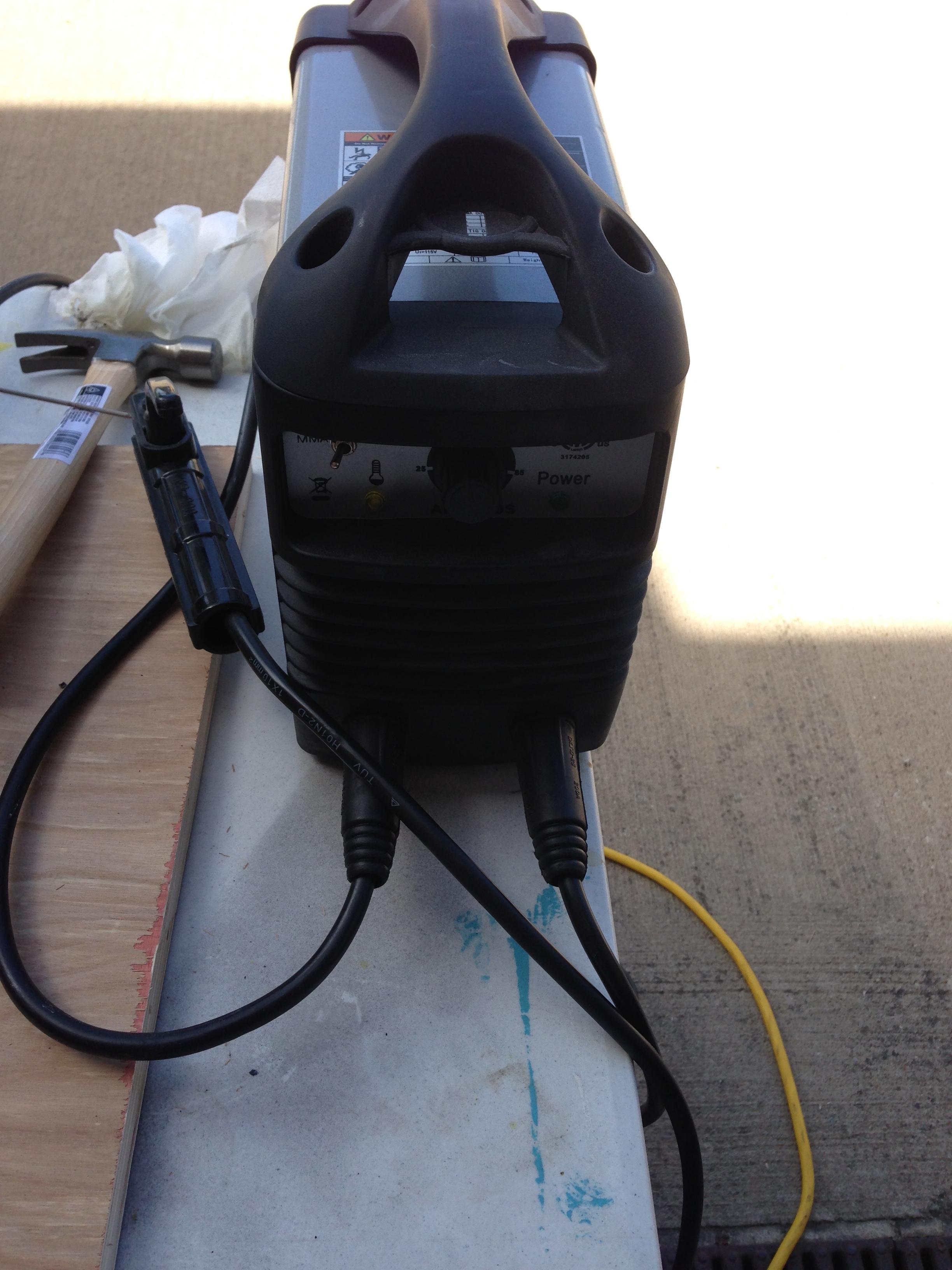
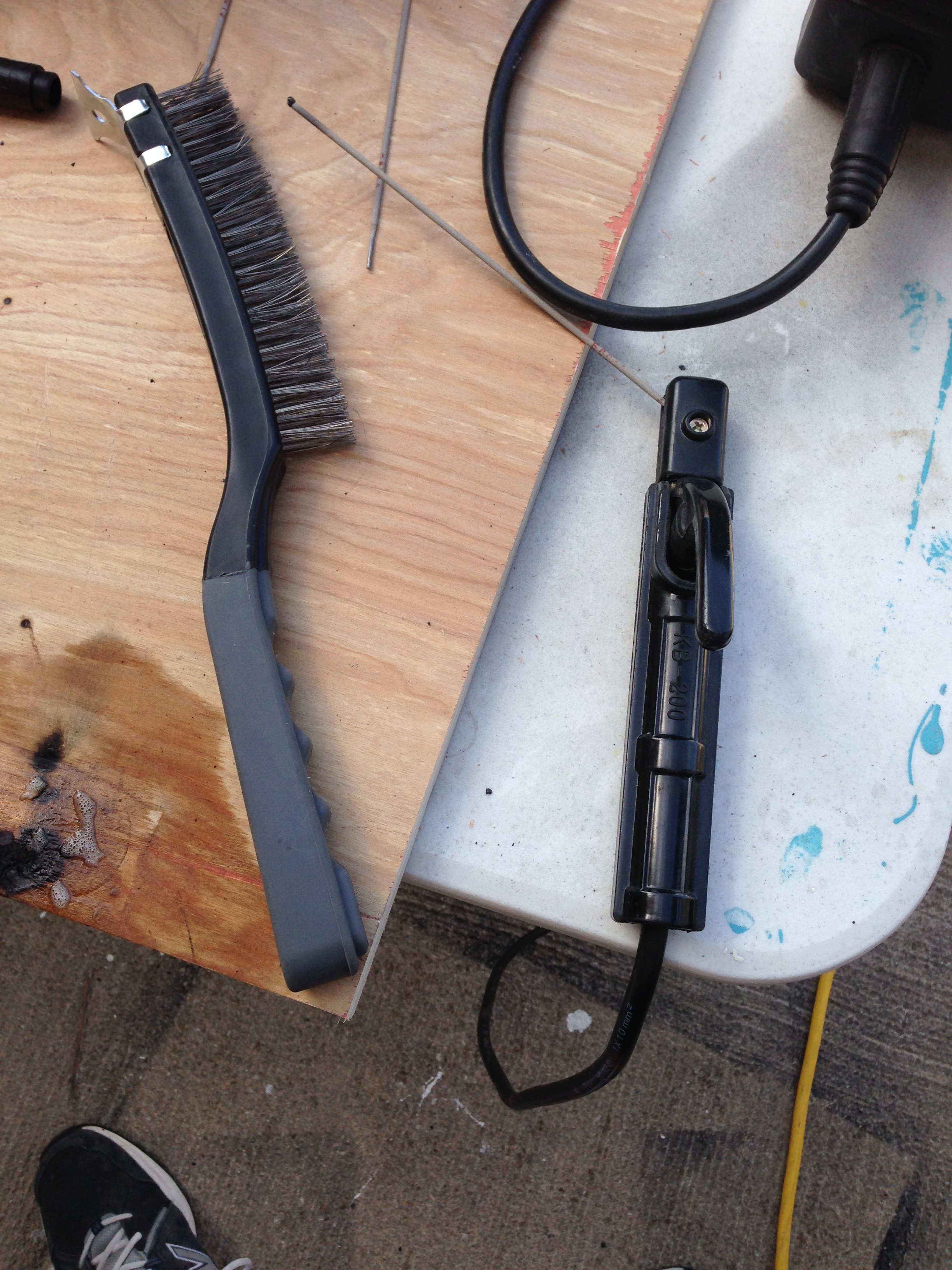
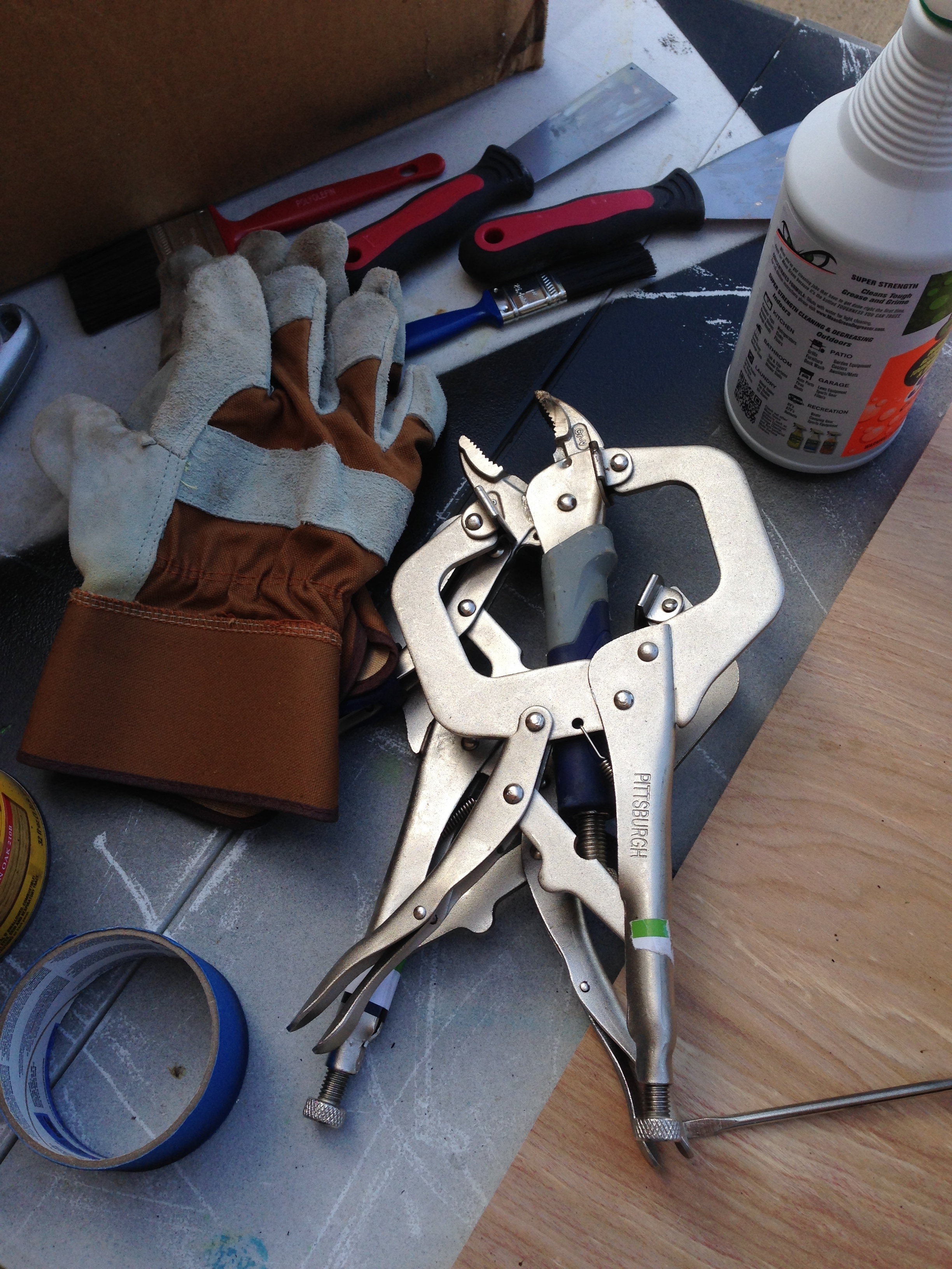

The welder was about 100 bucks from Costco. The face mask is an aut0-dimming one from Harbor Freight, which worked great. I bought some welding rods from Harbor Freight, which worked out great. I should have practiced a bit before I welded my part, but I really didn’t have anything to weld on. Anyway, it turned out ok for my needs. I was surprised how well this $100 welder actually worked. I’m sure it will only handle small jobs, but in general that’s all I really have.
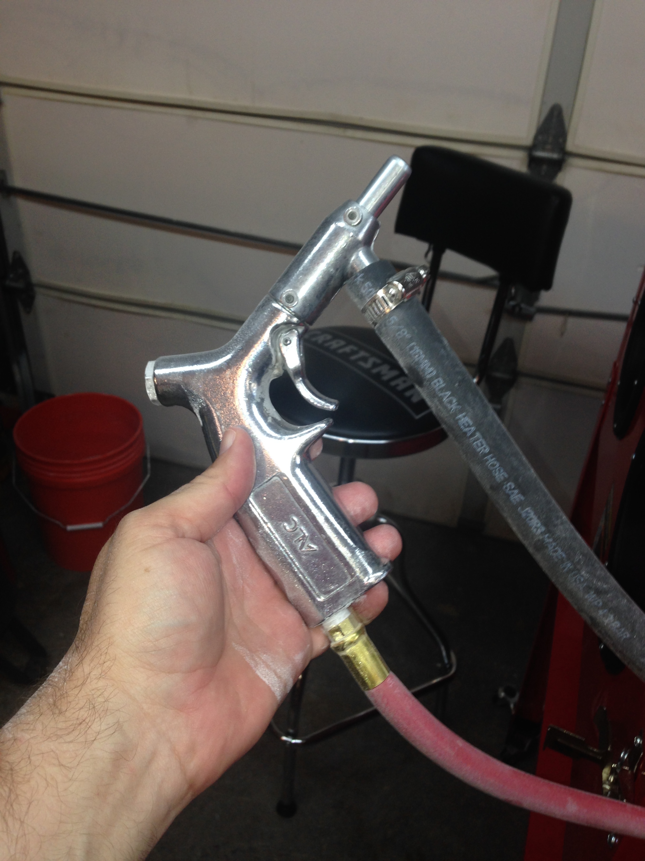
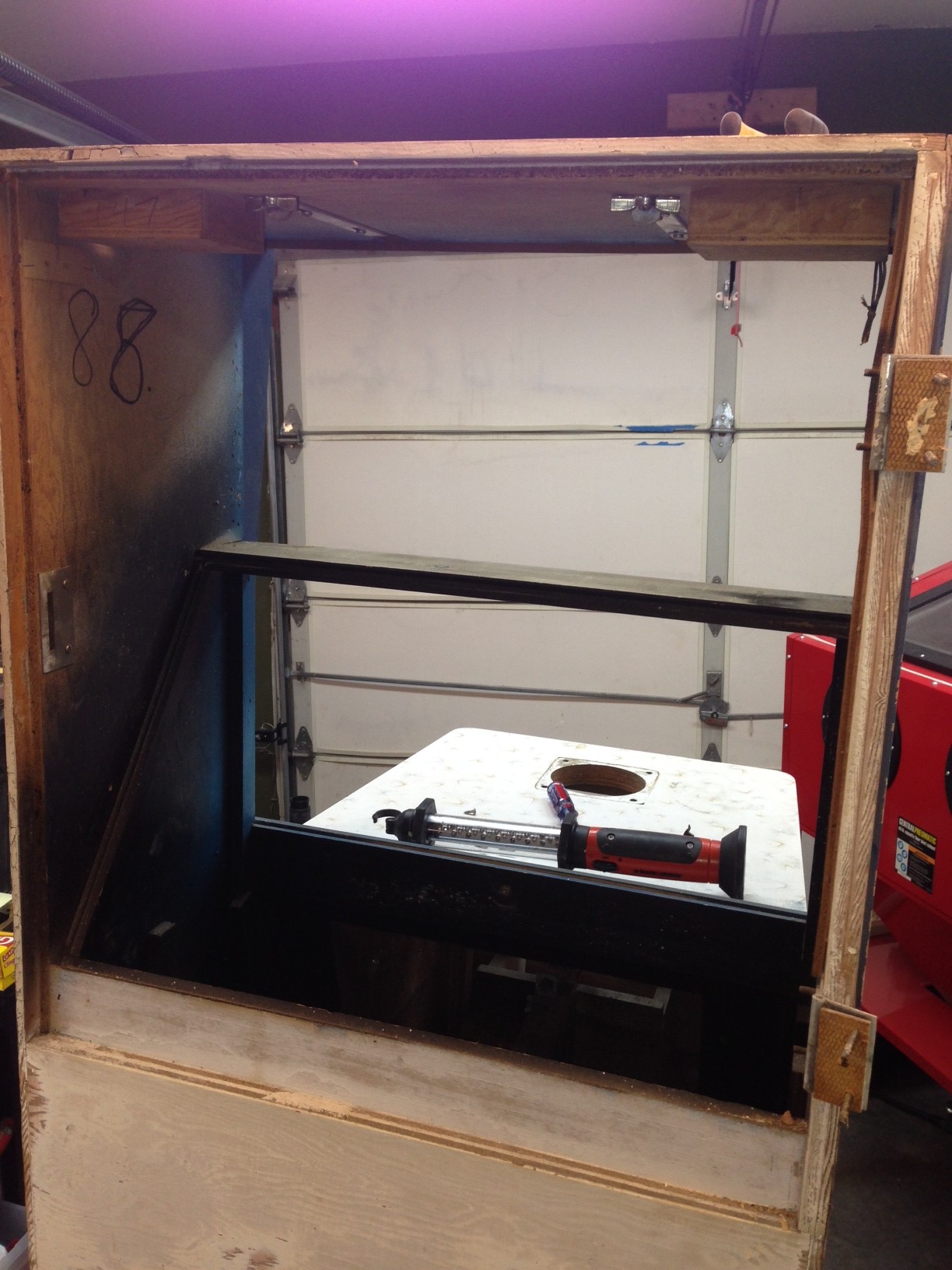
Media Blasting
I finally got my new blasting cabinet up and running. I bought a Harbor Freight cabinet, and it was a bear to put together. Once I get it all ready, the gun wasn’t working right and I ended up getting a new gun from Northern Tool.
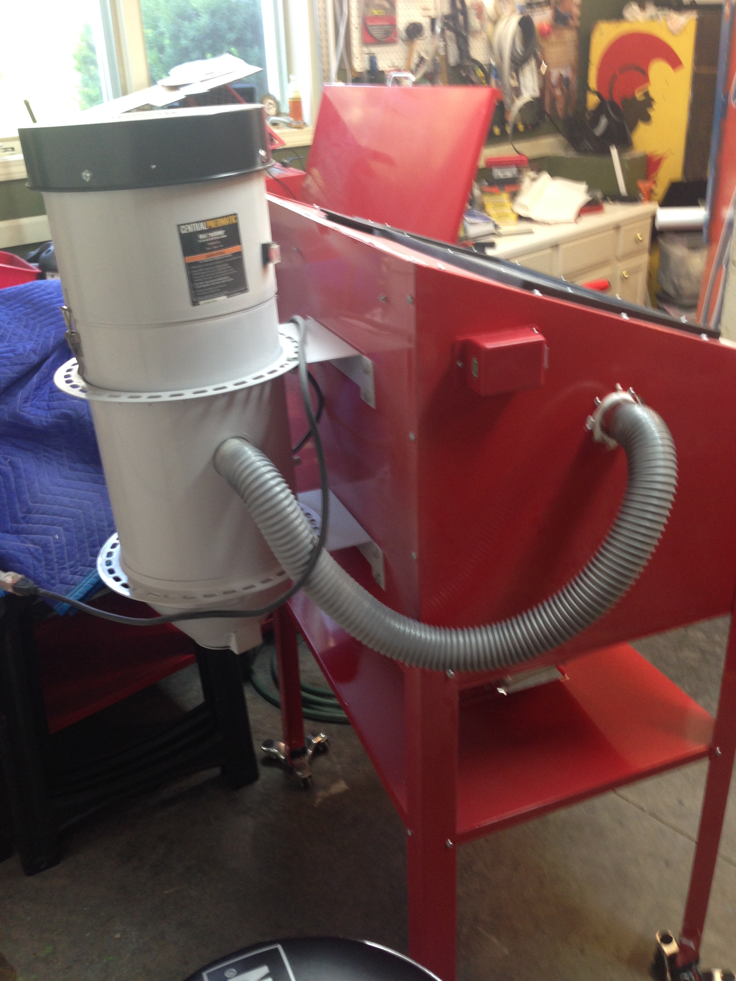
Now that the blaster cabinet is up and running, I was able to take care of the gun assembly and coin door, as well as the gun barrel. All were in various states of flaking paint and/or rust. You can see before pictures earlier in this post.
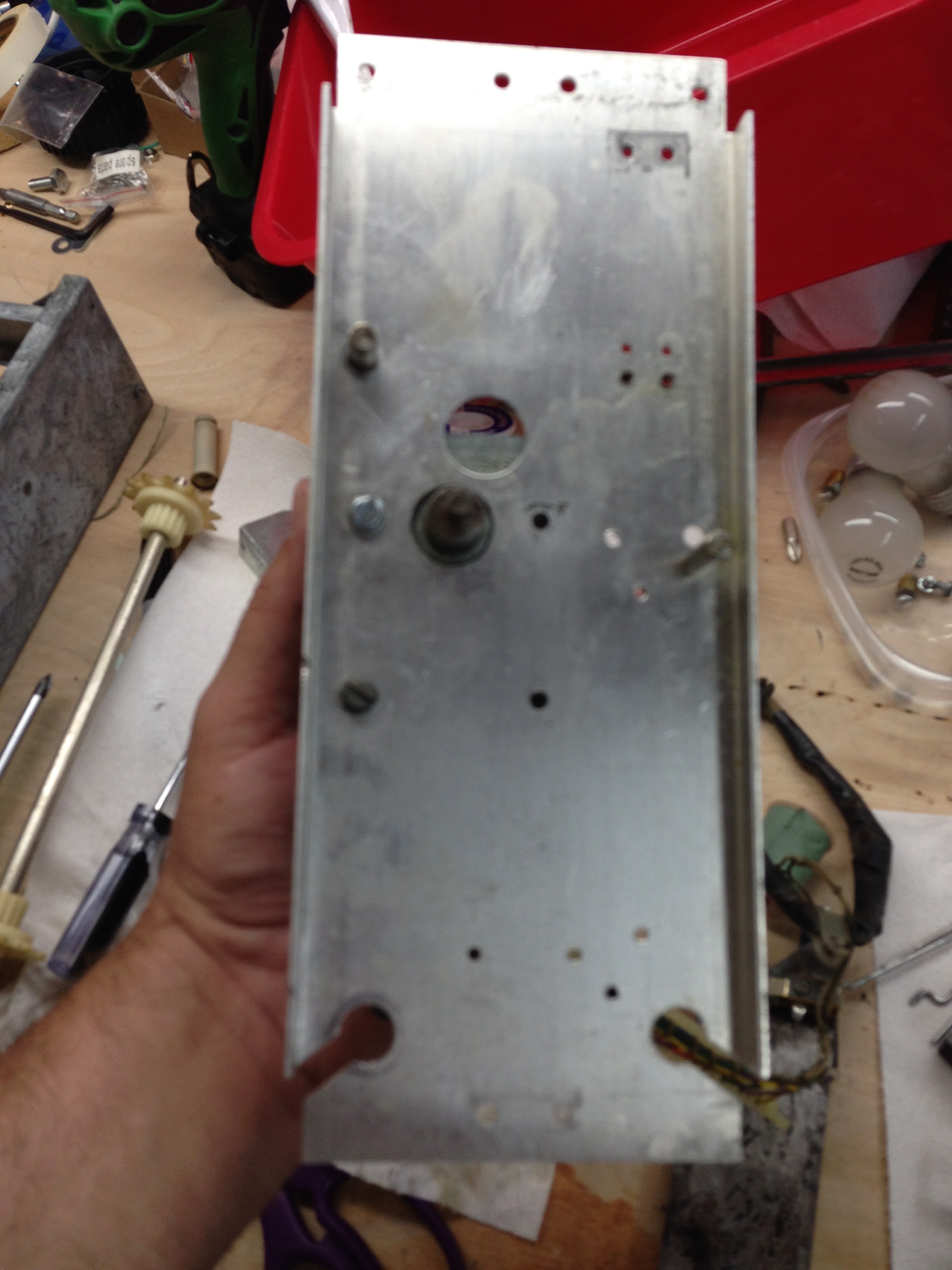
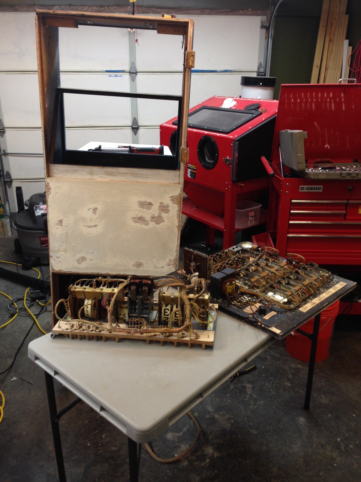
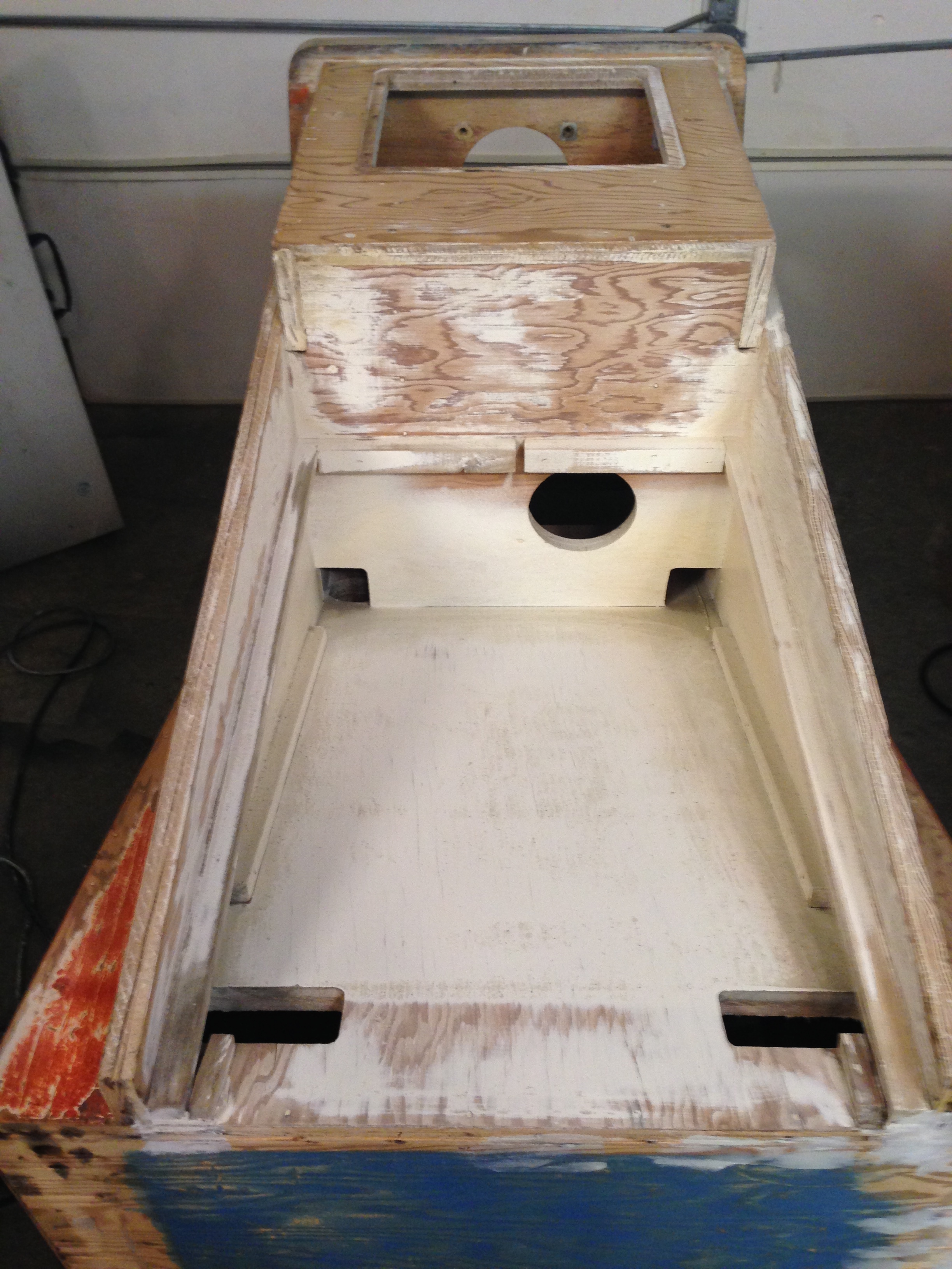
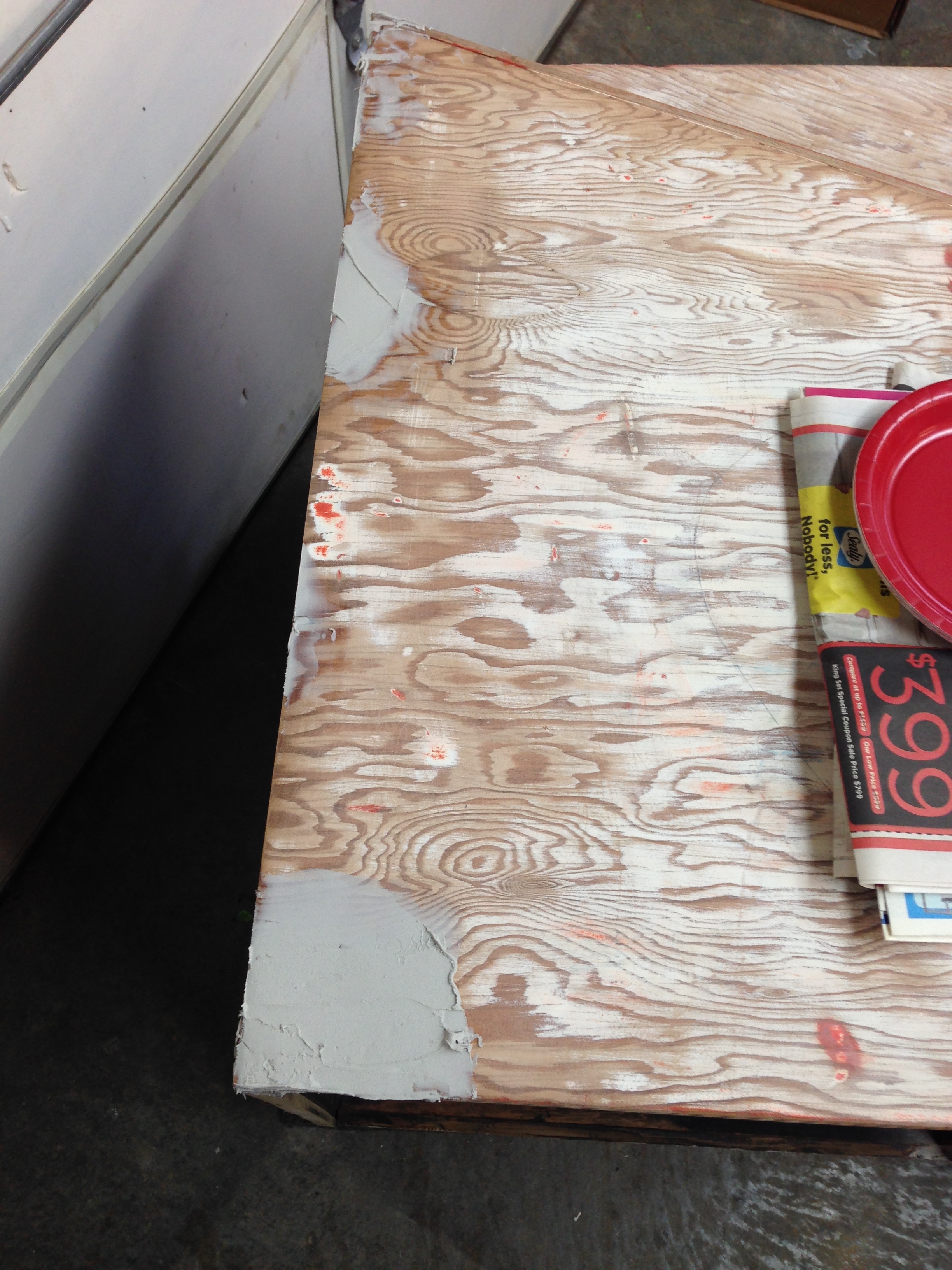
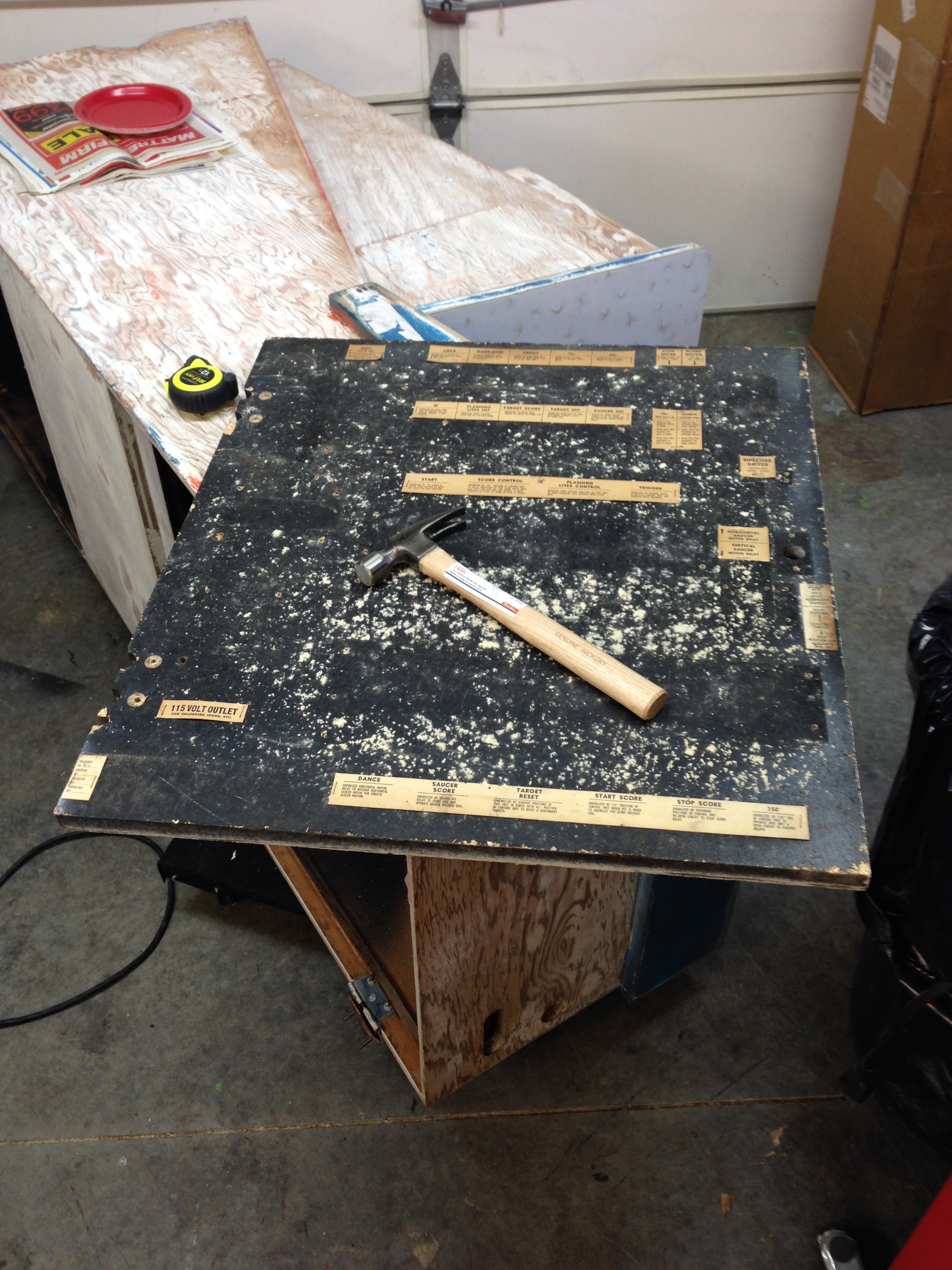
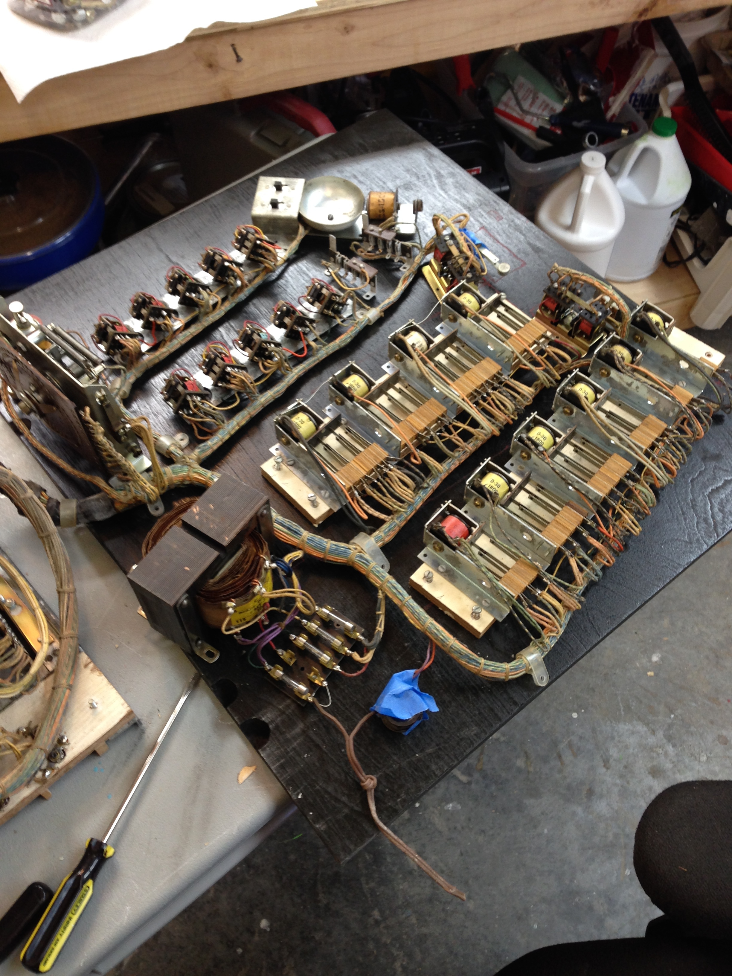
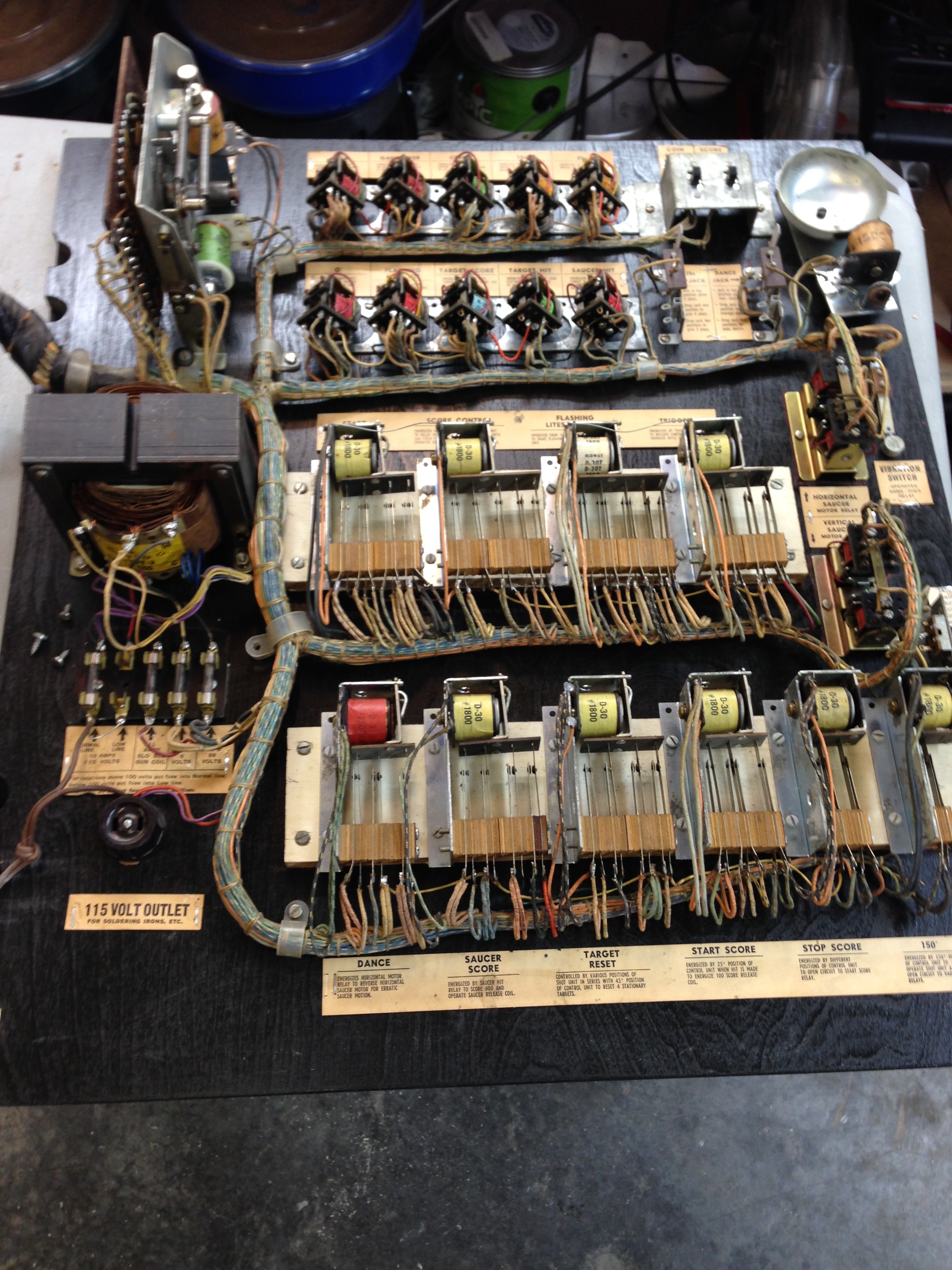
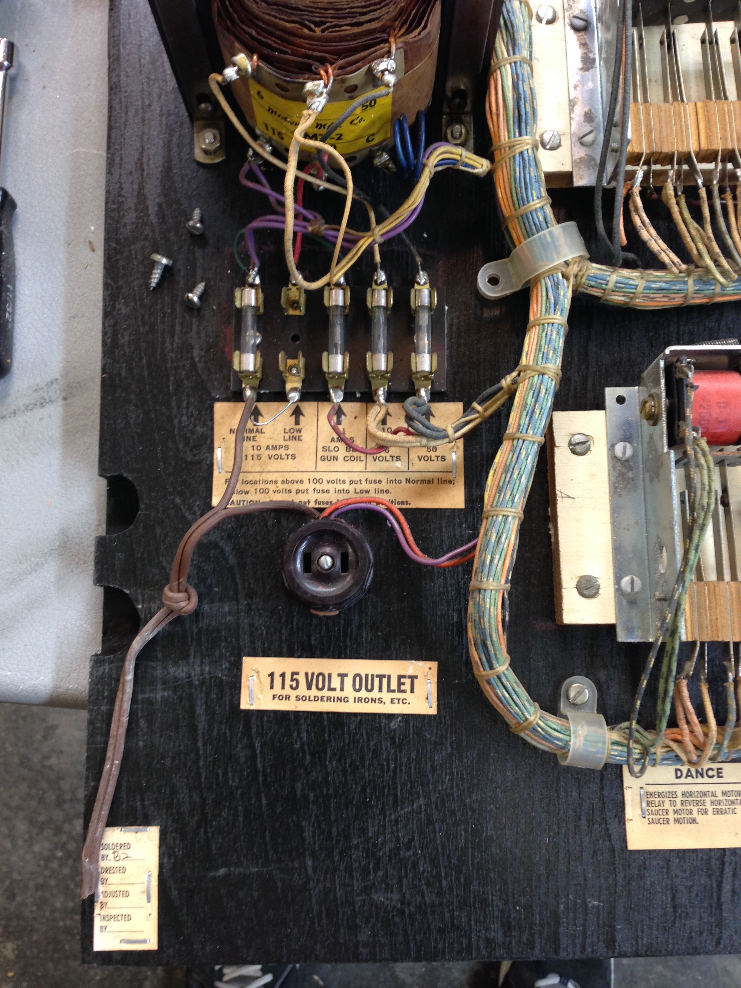
I removed the remaining cardboard inserts today to start the rough finishing of the cabinet. I decided the particle board they used for the two back panels was in too rough shape (after trying to sand them) to keep. I’ll be making replacement panels from plywood. For the bottom panel, it’s no big deal, but for the top panel, I have to remove all the electronics and replace them on the new board. This will be some work, but if I don’t do it, that particle board is just going to keep deteriorating.
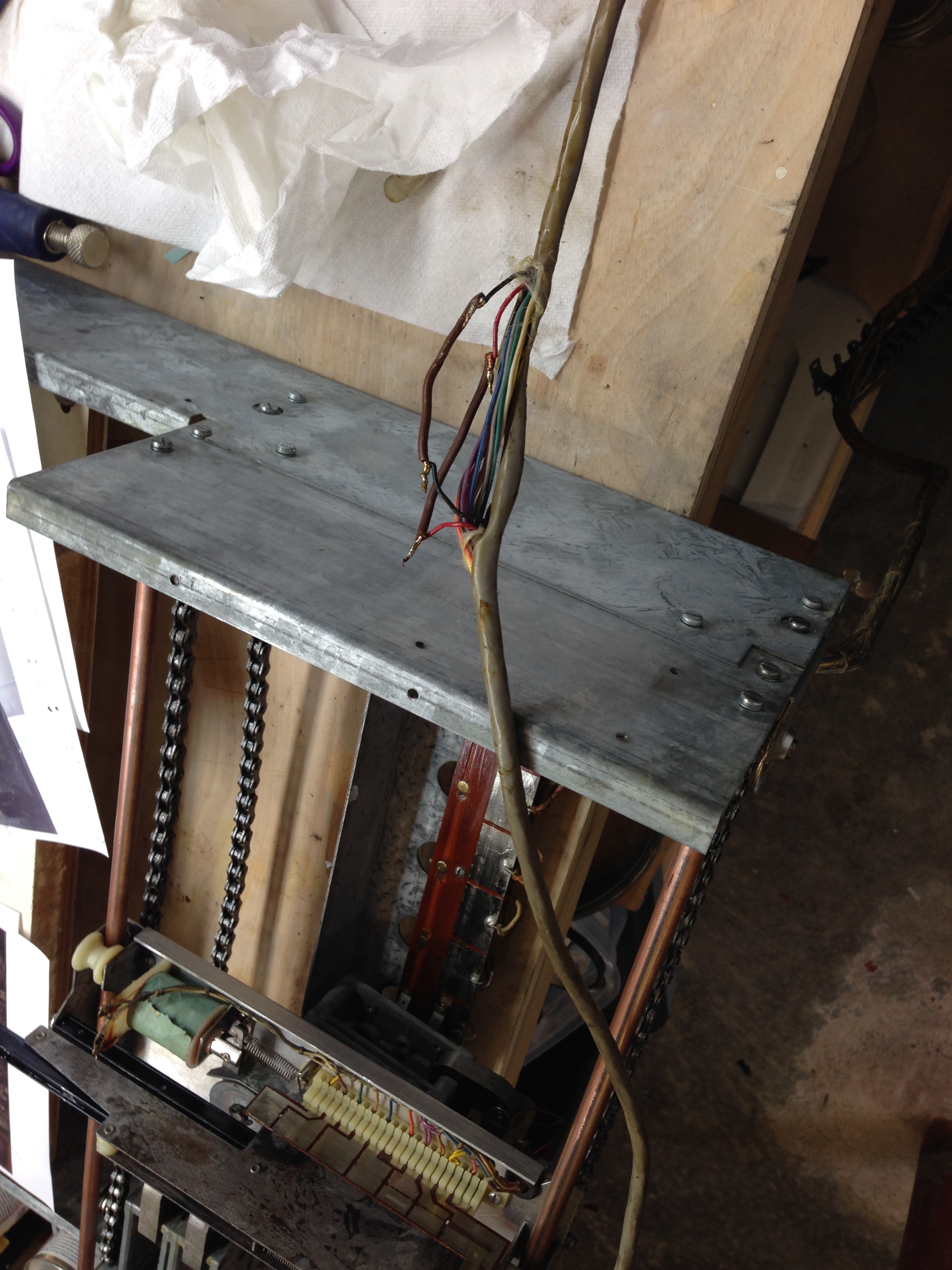
In order to remove the back panel, you have to remove the wiring harness from the cabinet (unless you want to unsolder tons of connections)! The back door, score reels, and wiring harness that goes down inside the cabinet to the gun assembly, and then on down to the bottom target assembly. This was a ton of work to get all this out without breaking anything.
I do have a jones plug that is broken and needs to be fixed. I think I may try JB Weld for this.
Paint – Tracing and Stenciling
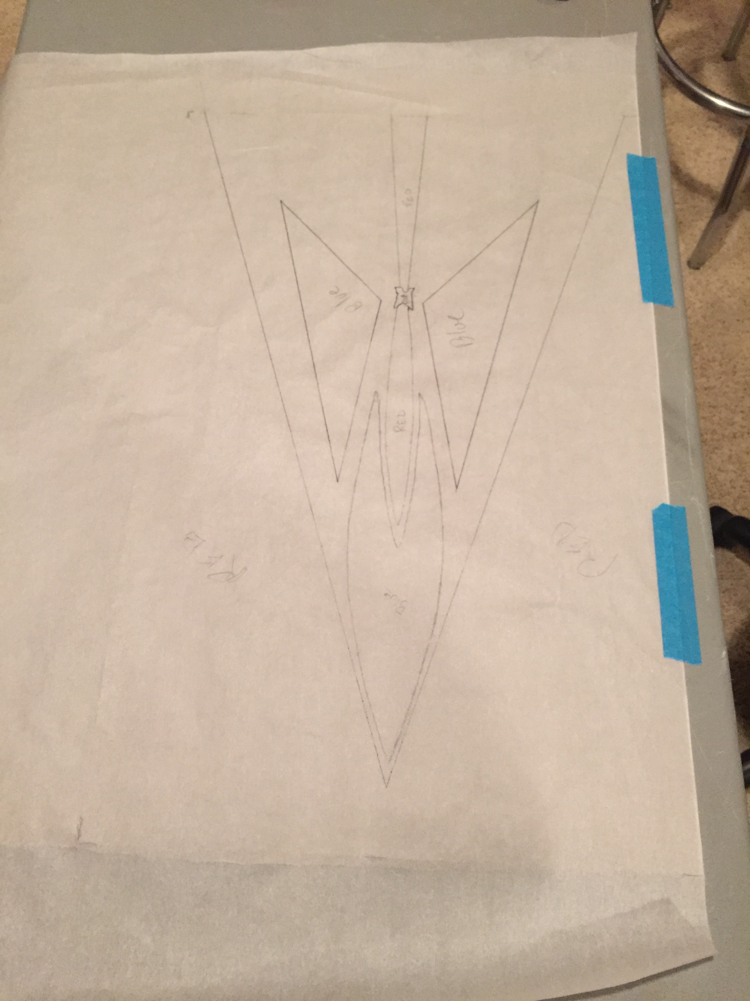
I bought some tracing paper from Amazon to trace the patterns on the sides of the cabinet. This worked out pretty well. I’ll make stencils from these tracings once I have the cabinet fully sanded and primed. In the past, I’ve used scrap cardboard for my stencils, but I decided to try out some purpose made stencil material. I found and ordered this stencil material. I haven’t got it yet, so I don’t know how well it will work out. I’ll update when I start that part of the project. I used some french curve templates to help correct some of the arcs that were not done very well in an earlier repaint.
Cabinet Preparation
I’ve got the cabinet pretty much ready for paint. One side sanded down pretty well with 60 grit sandpaper, but the other side had thicker paint which kept gumming up the sandpaper, so I stripped it with paint stripper. I’ve filled a number of gouges, chips, and one place where a whole chunk of wood was missing with Bondo. I then sanded the whole cabinet with 150 grit. Every time I finish sanding and blowing off all the dust, I find more areas I need to fill/sand. I think I’m getting to the point of diminishing returns. I always have to remind my self the enemy of good is better…
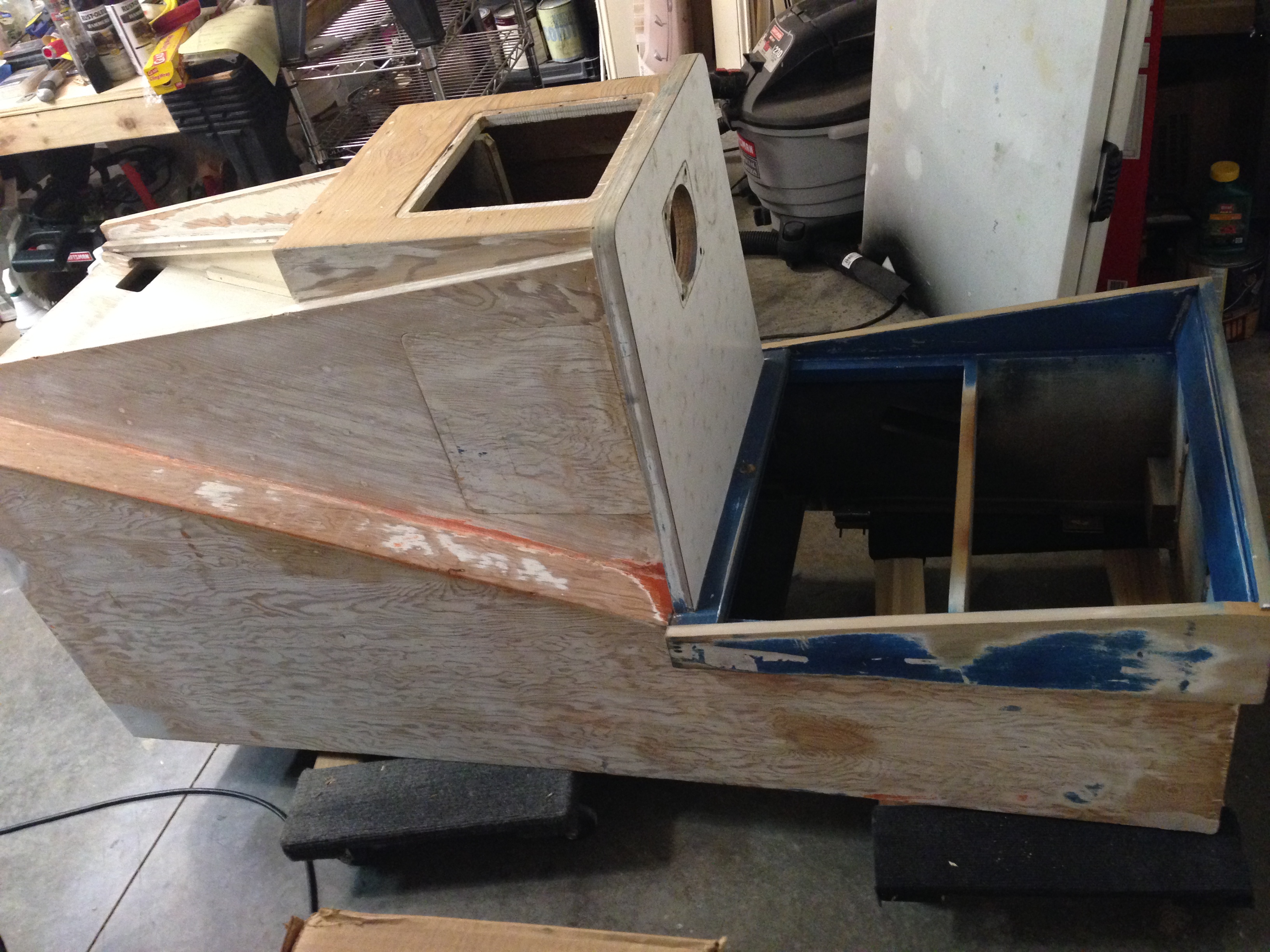
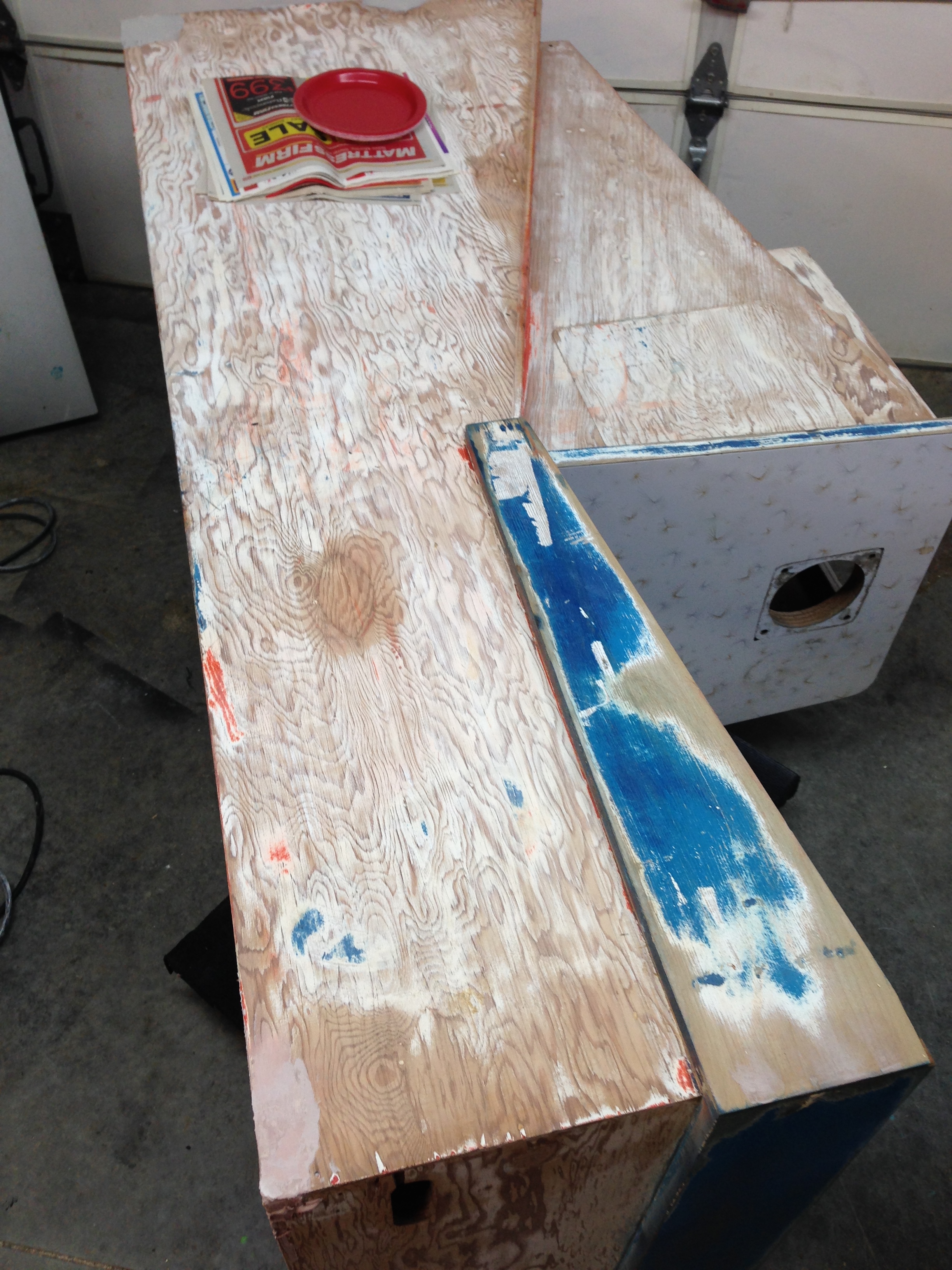
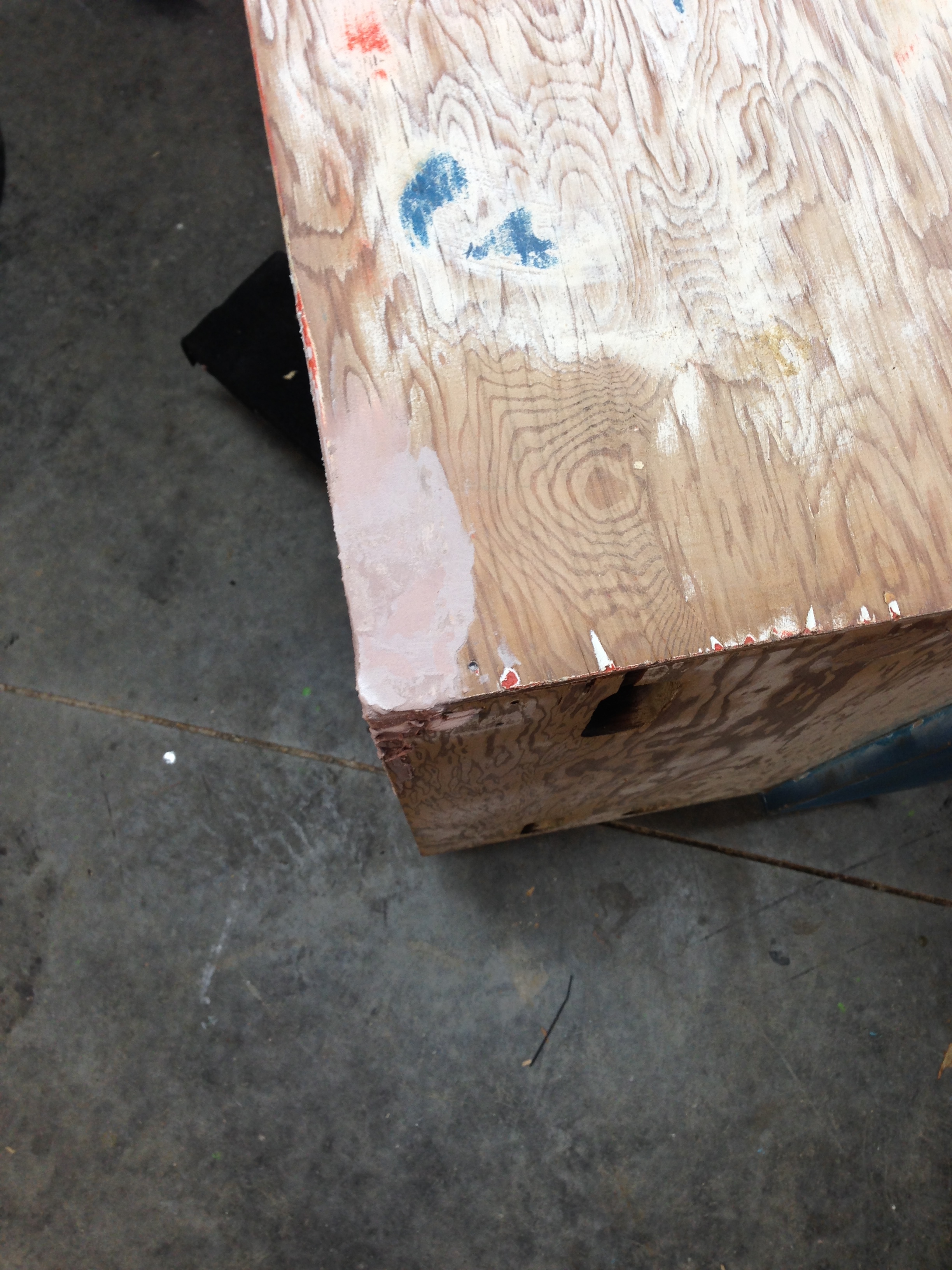
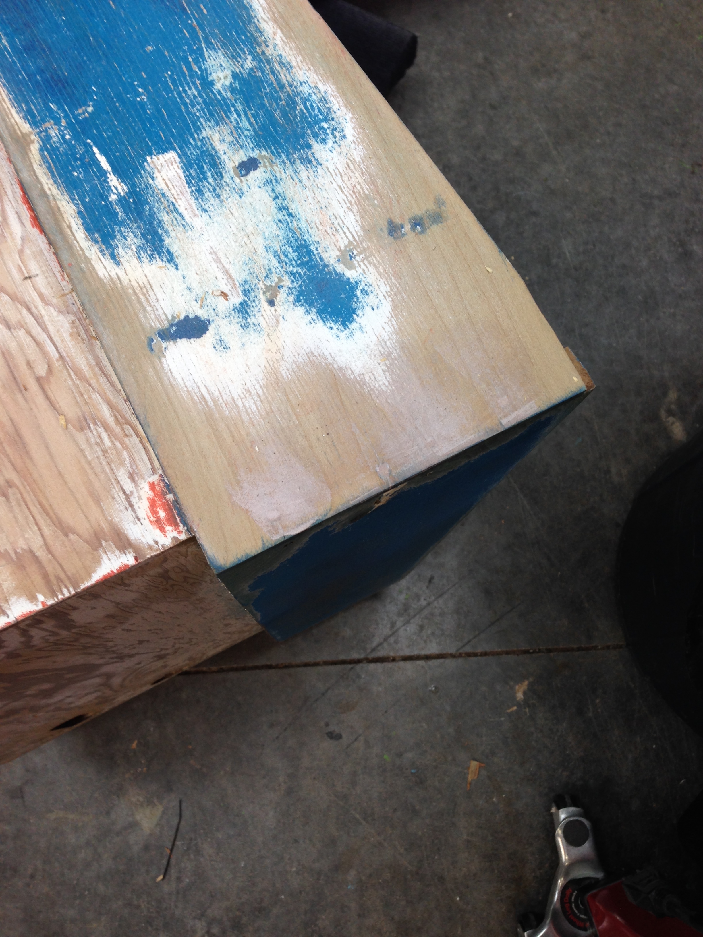
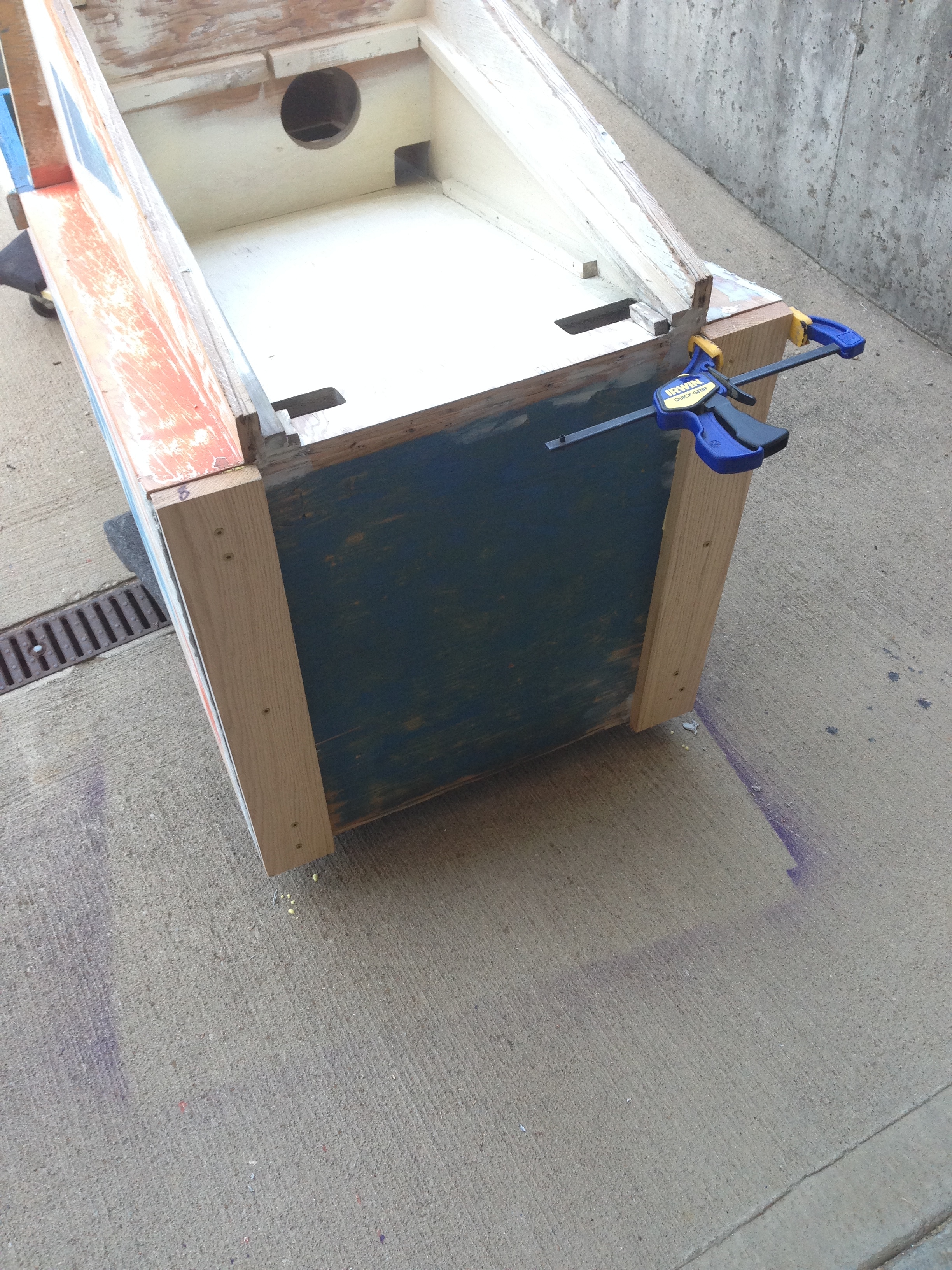
The two 1×4 runners that went along the bottom of the cabinet were pretty dry-rotted, and were falling apart at the corners, so I removed them, sanded the bottom, filled the holes with Bondo, and made two new 1×4 stripps. I’ll drill holes, and mount brackets for adjustable feet soon.
Paint Color Matching
I’ve used the Sherwin Williams Color Snap app before to capture paint formulas for colors, and generally it seems to work pretty well. I took a picture of the paint on my cabinet (after I sanded through the repaint to try to get to the original color) and of a picture from Clay’s site to see what the app would say for the colors. I think Clay’s picture is more true to the original color. Here’s the photo I used to match the color. 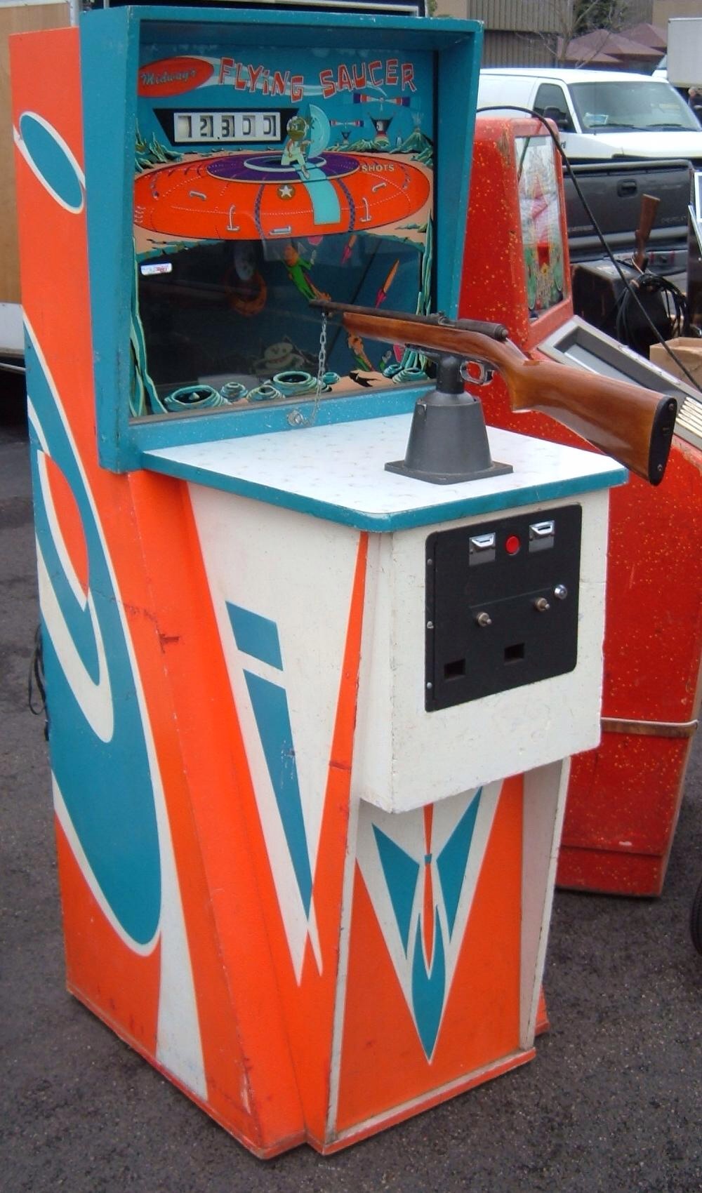
And here’s the colors Sherwin William’s says are the “blue” and “orange” colors.


Looks pretty good to me, not that I see colors very well, but these seem like a good match. Guess that’s what I’ll go with.
Rear Door & Electronics
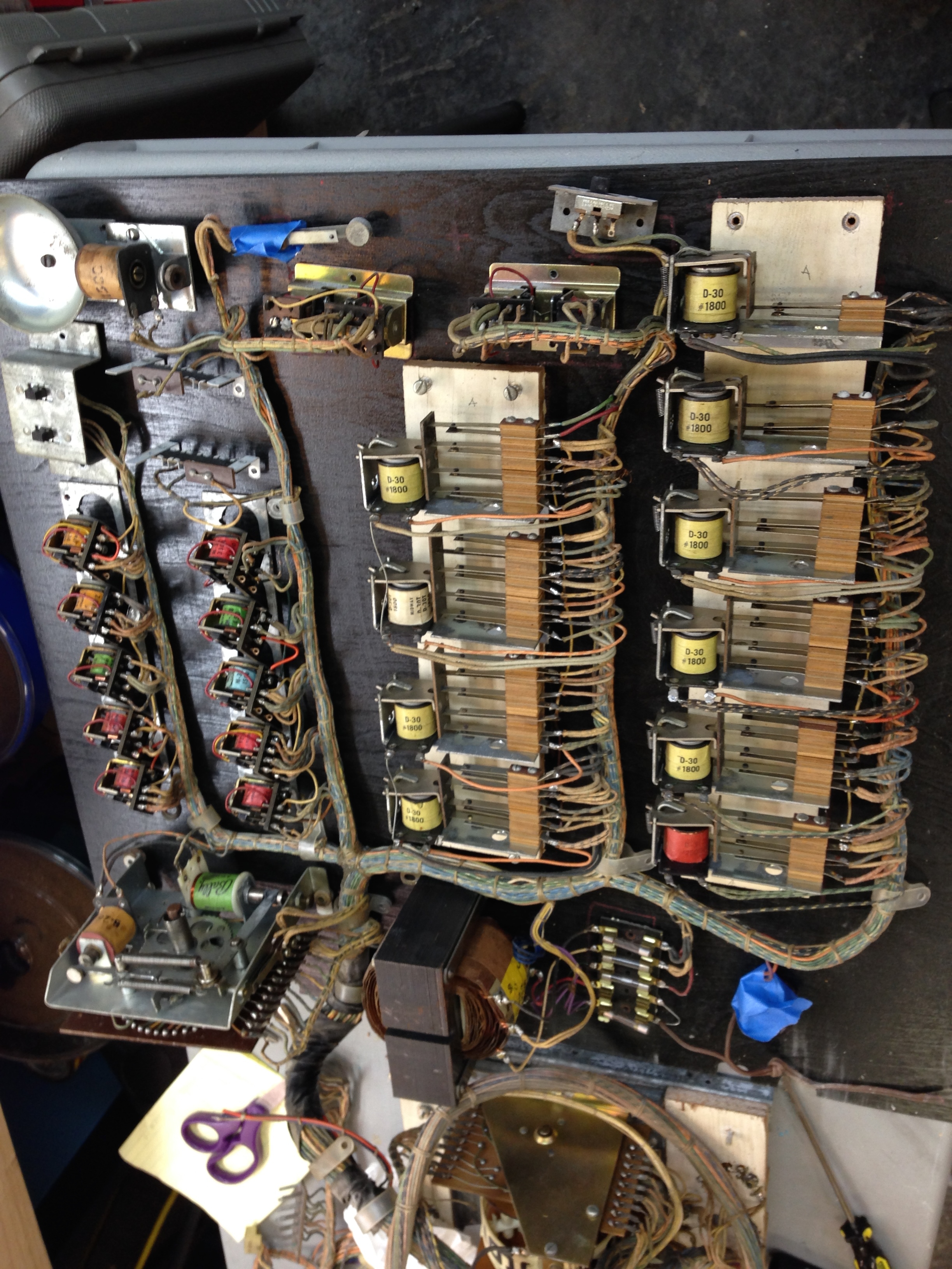
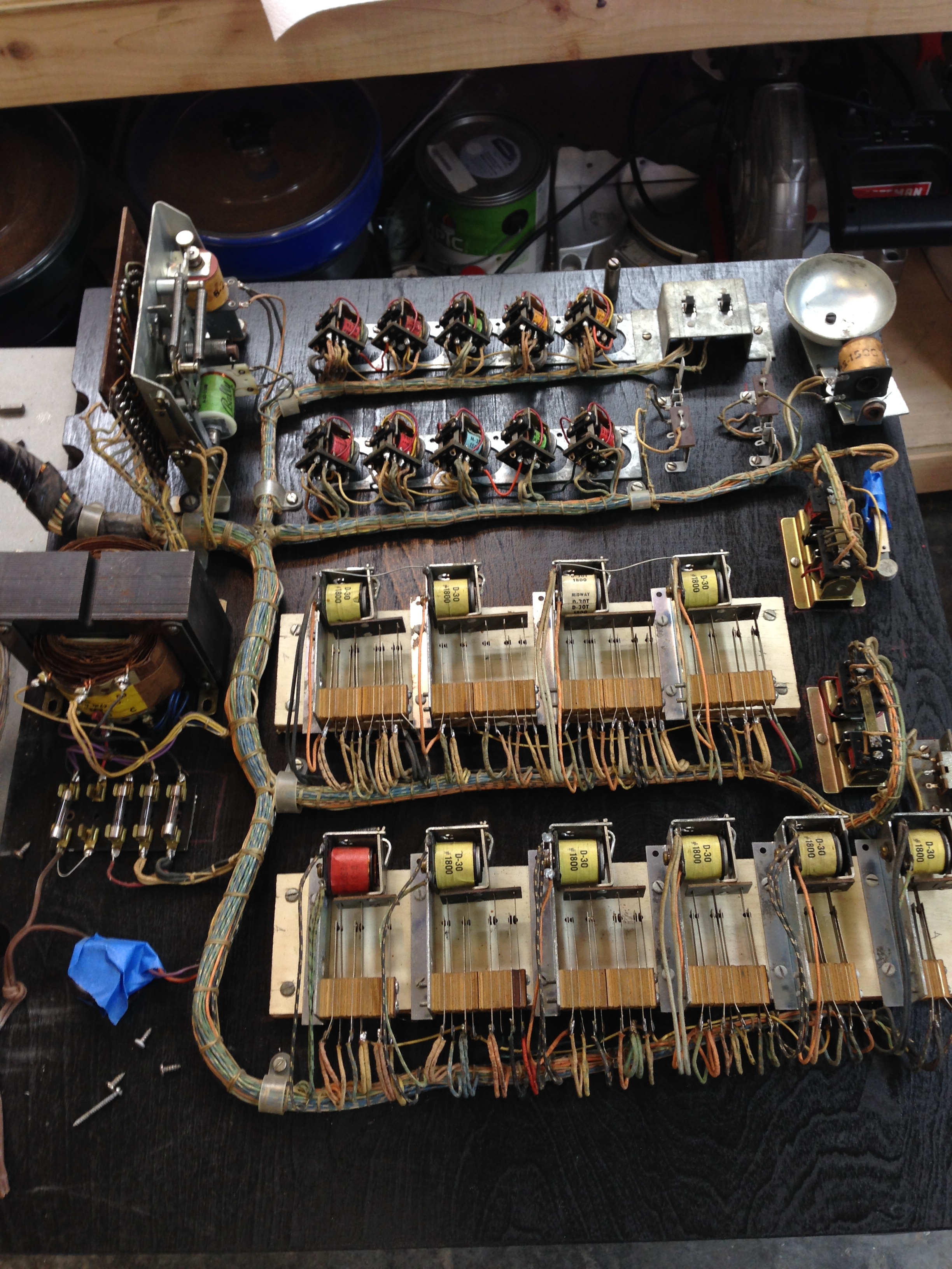
I cut a new back door from 3/4 birch plywood, sanded it, and painted it with matt finish black spray paint. I then had to move the electronics from the old (particle board ) rear door to the new door. Rather than unsolder everything, I decided to try to remove all the screens and then just “slide” all the electronics from the old door to the new door. This actually worked out pretty good as the wiring was well done, and pretty stiff, so I could sort of slide the old door out from under the electronics, while sliding the new door in. The transformer was very heavy and that needed some special handling, but all in all this went well. When the cabinet is painted, I’ll fit the door in the opening, match up the hinges, and drill the holes to make sure they are positioned correctly.
Coin door Repaint
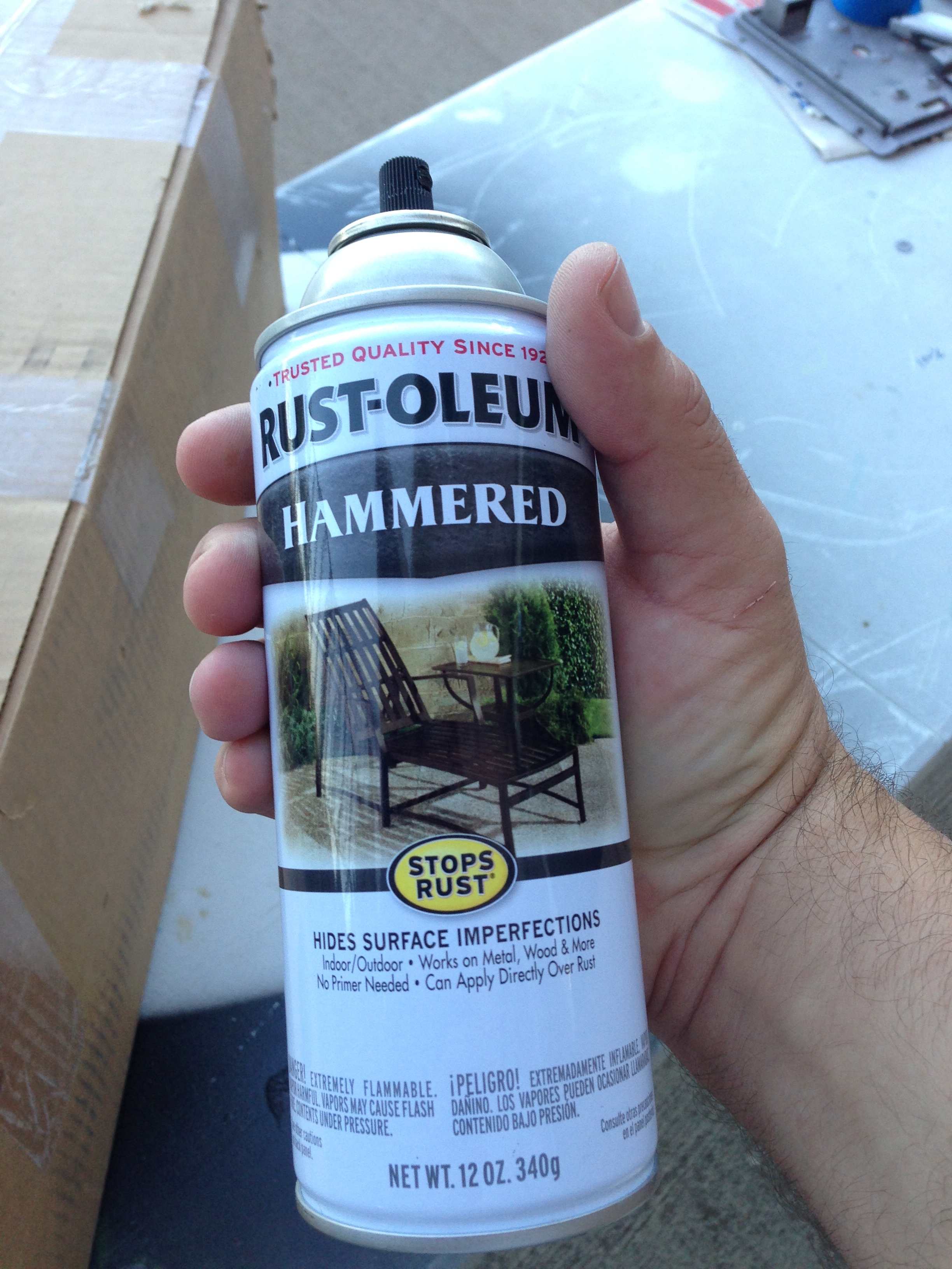
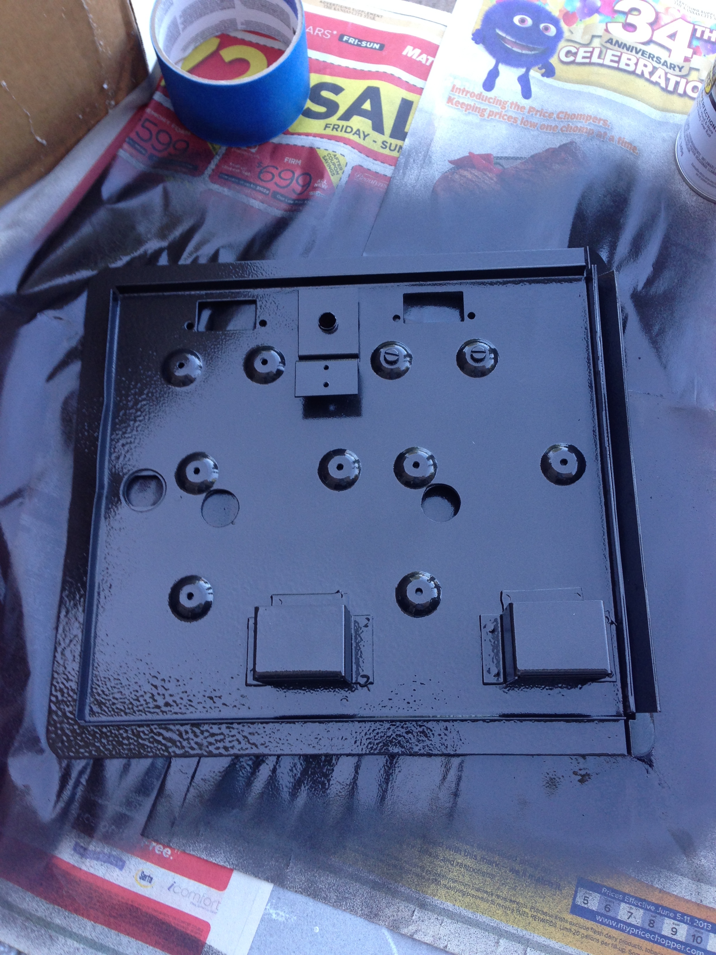
I decided to use hammer tone black gloss spray paint on the coin door. After I cleaned it up in the media blaster it was ready for paint.
Before:

After:
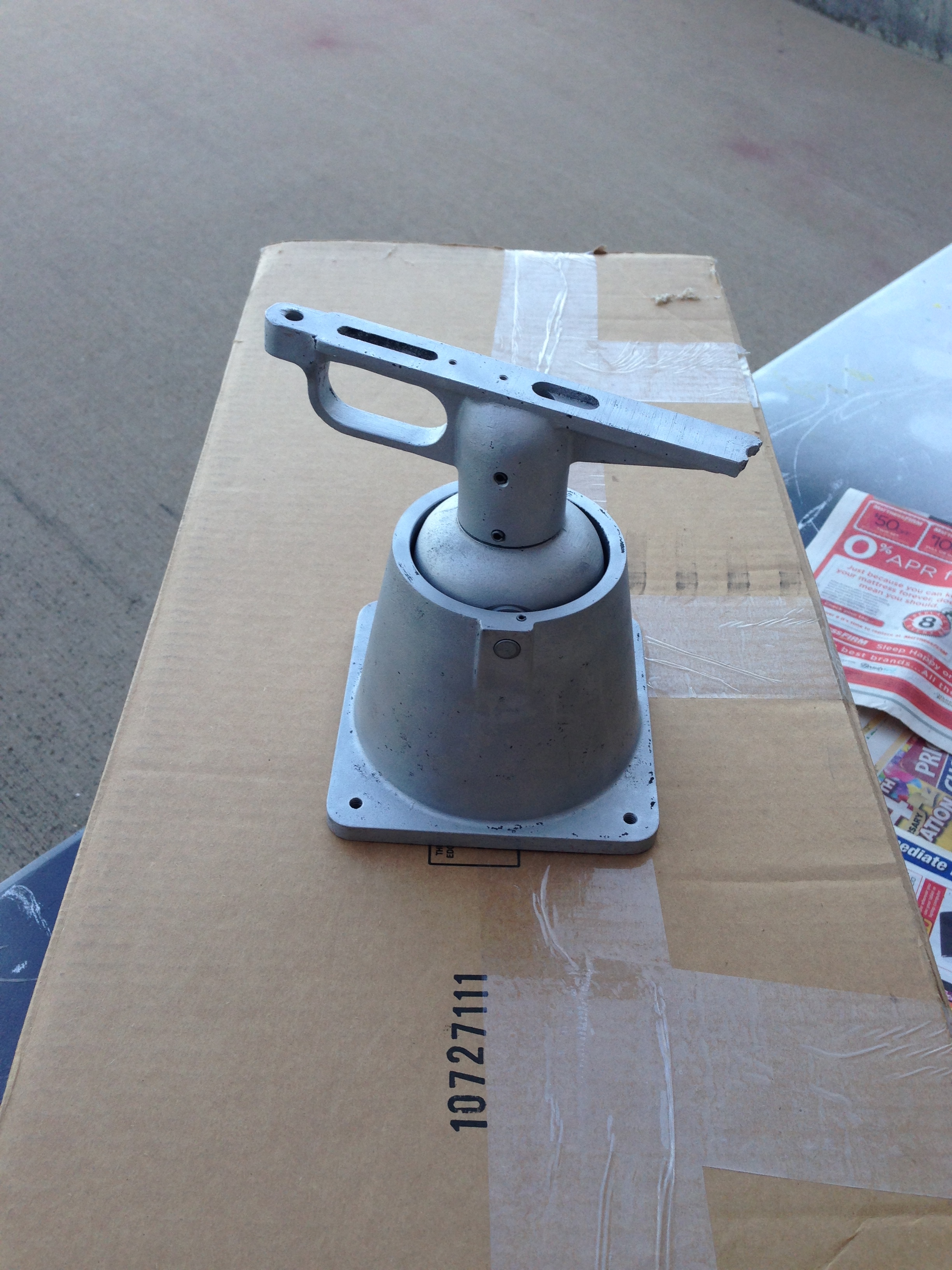
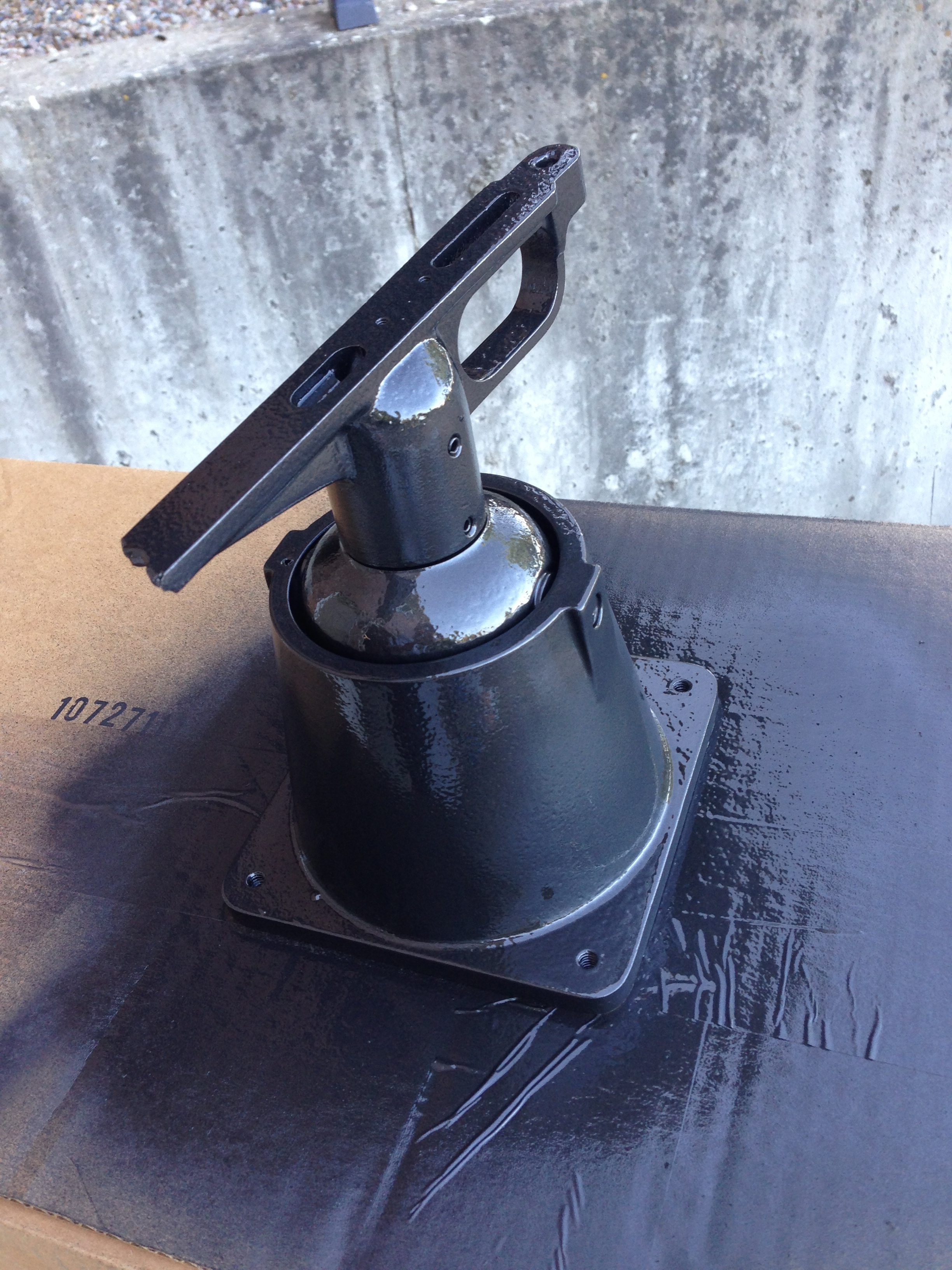
Gun Assembly Repaint
I used the same hammer tone paint on the gun assembly.
Before:
After blasting:
After paint:
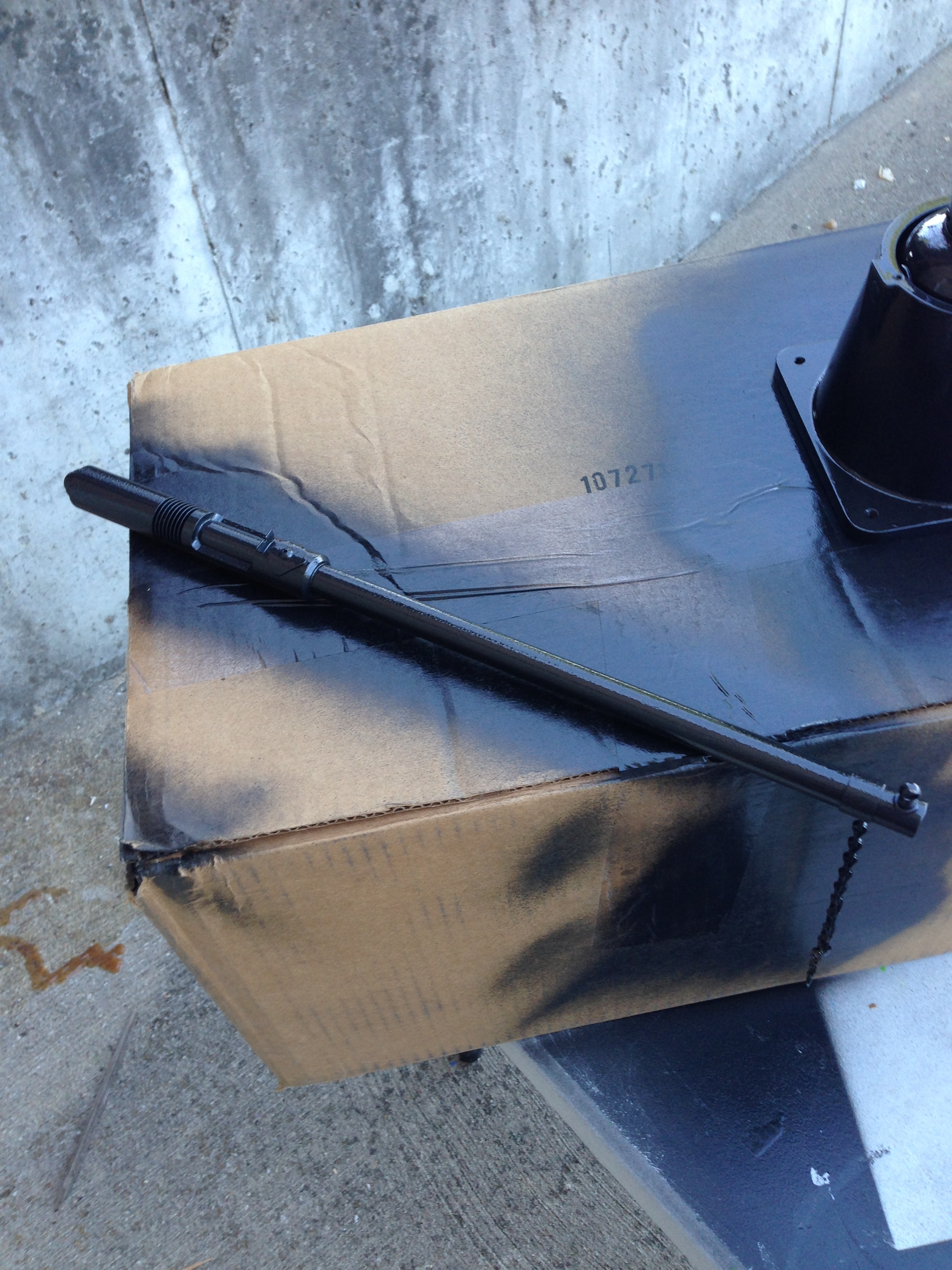
Gun Barrel Repaint
I used the same hammer tone paint on the gun barrel as well.
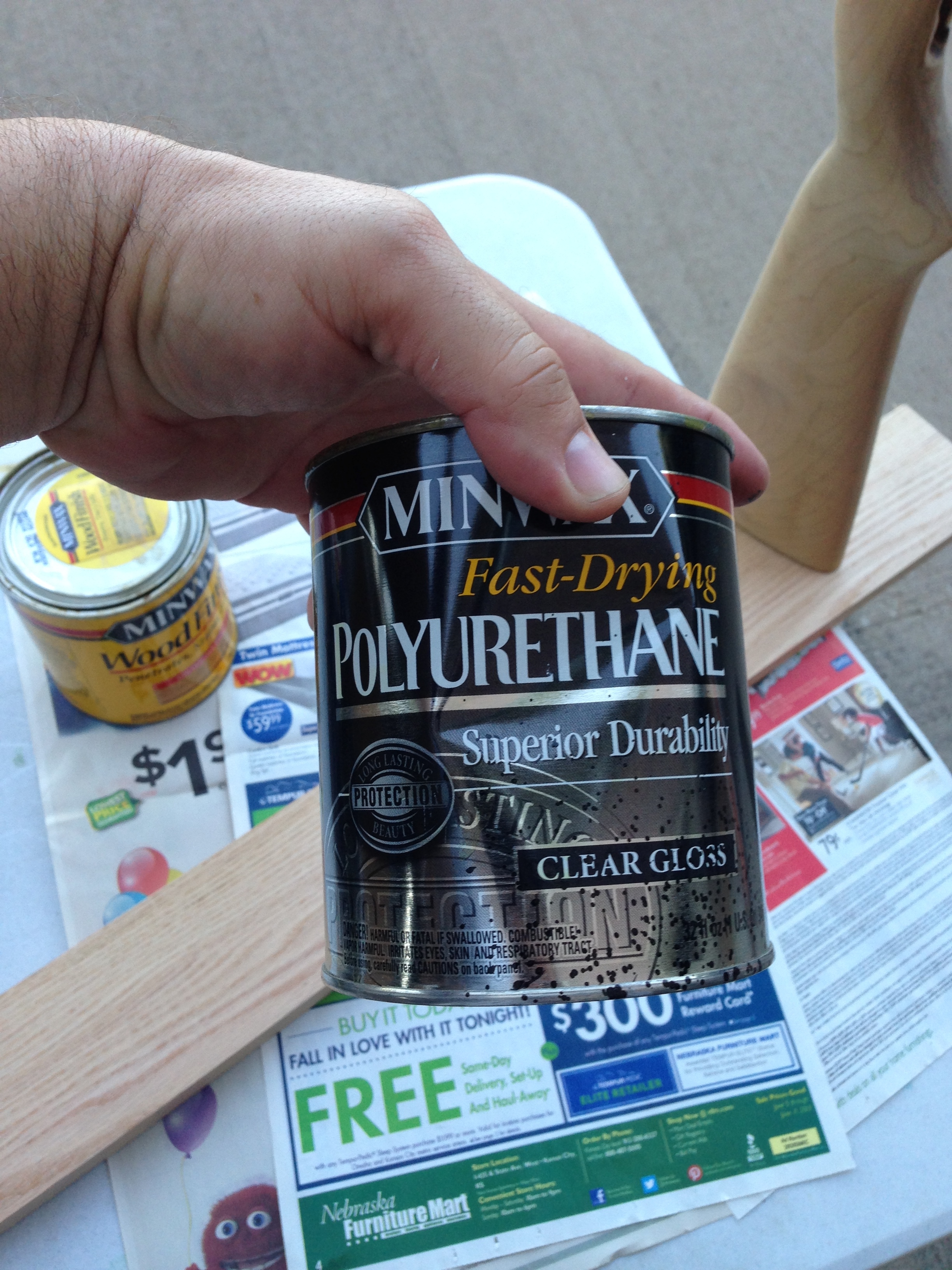
Gun Stock Refinish
The gun stock needed to be sanded, re-stained, and a good coat of polyurethane applied. I ran a screw up through a 1×4, and threaded it into one of the buttplate holes to hold the gun while I stained and clear coated it. This worked out great, as opposed to doing one side, letting it dry, and then the other…
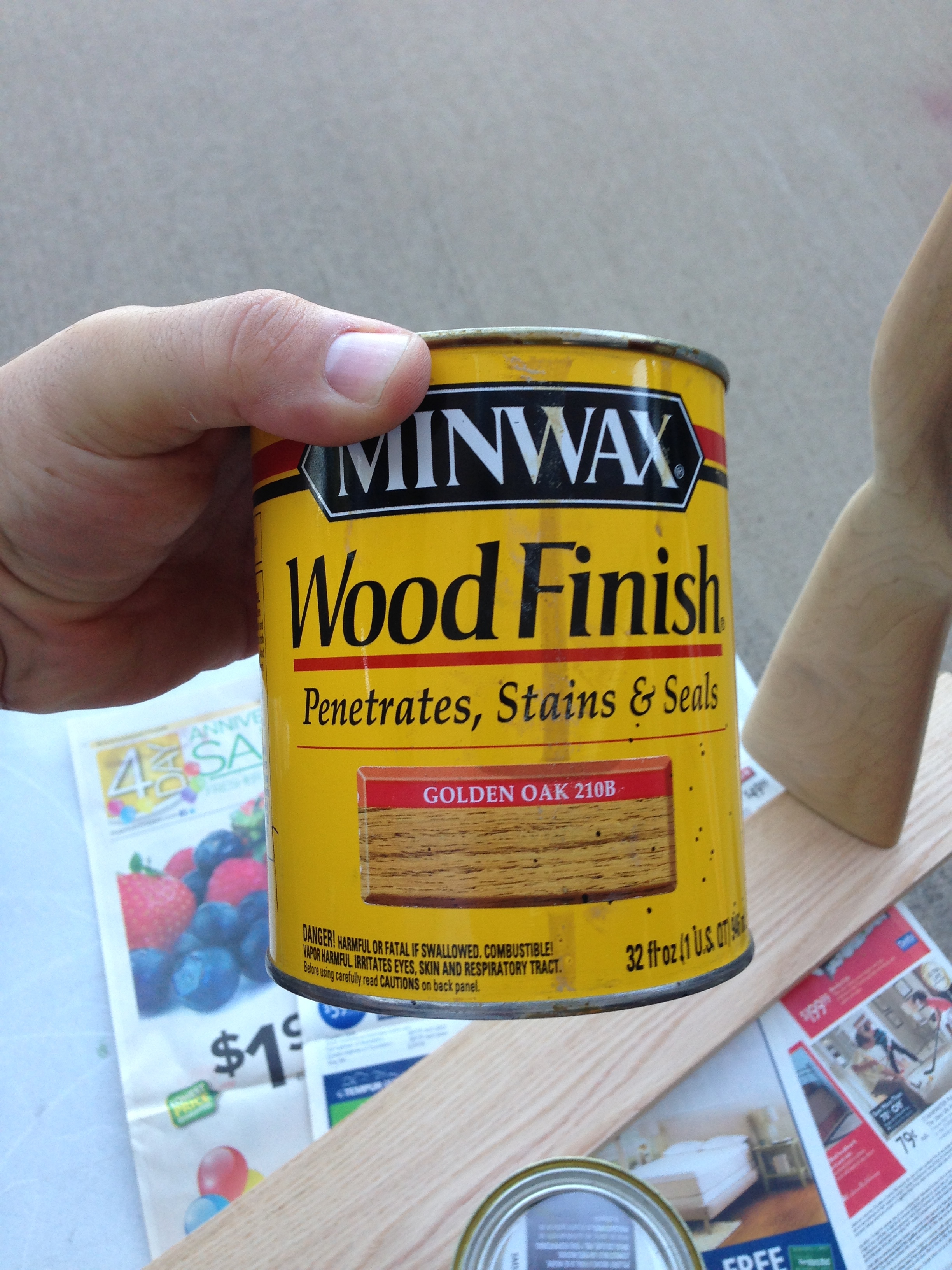
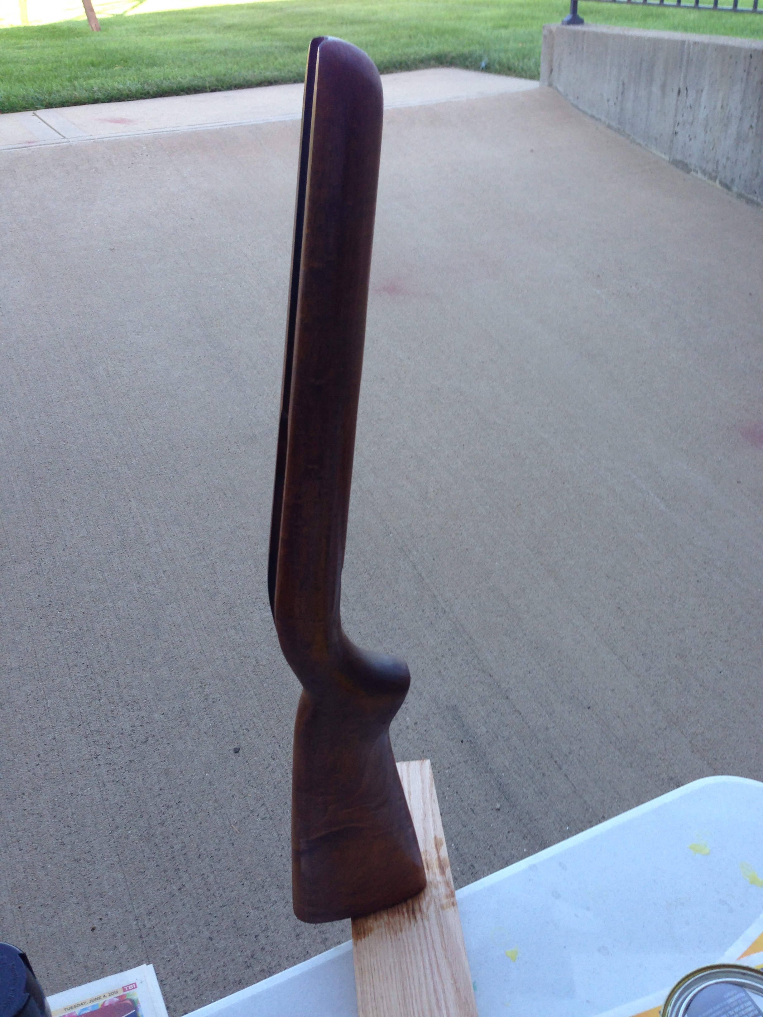
The last picture is before clearing the stock.
I had to order a butt plate for this gun stock. I wanted an authentic look and feel, and the current butt plate was just a homemade piece of wood that had been painted black and nailed on. It was chipping and falling apart. I removed it, and measured the gun butt and mounting holes to see if I could find a butt plate that would fit. I found that the size matched a “Marlin 37” rifle, and ordered the correct butt plate.
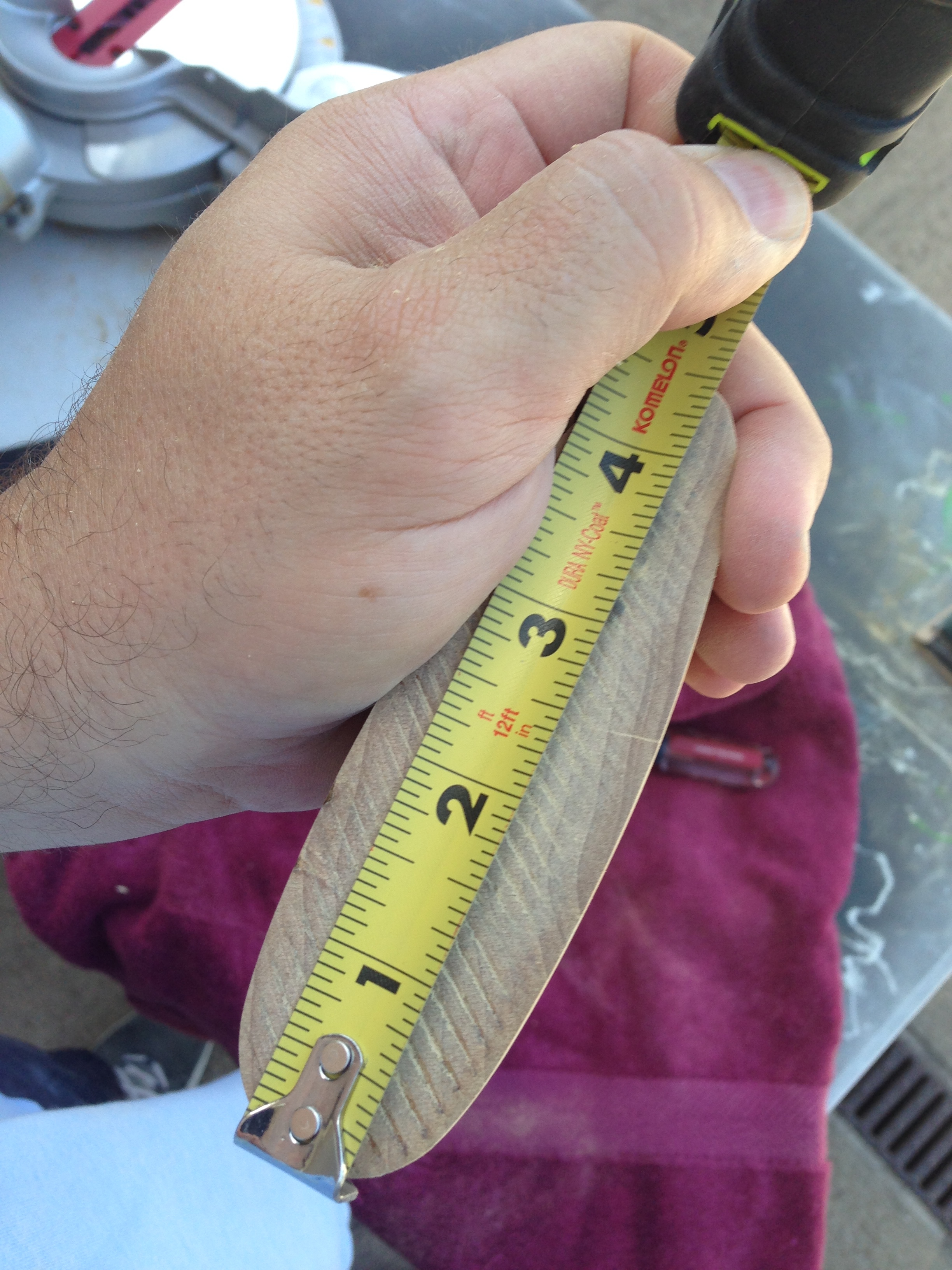
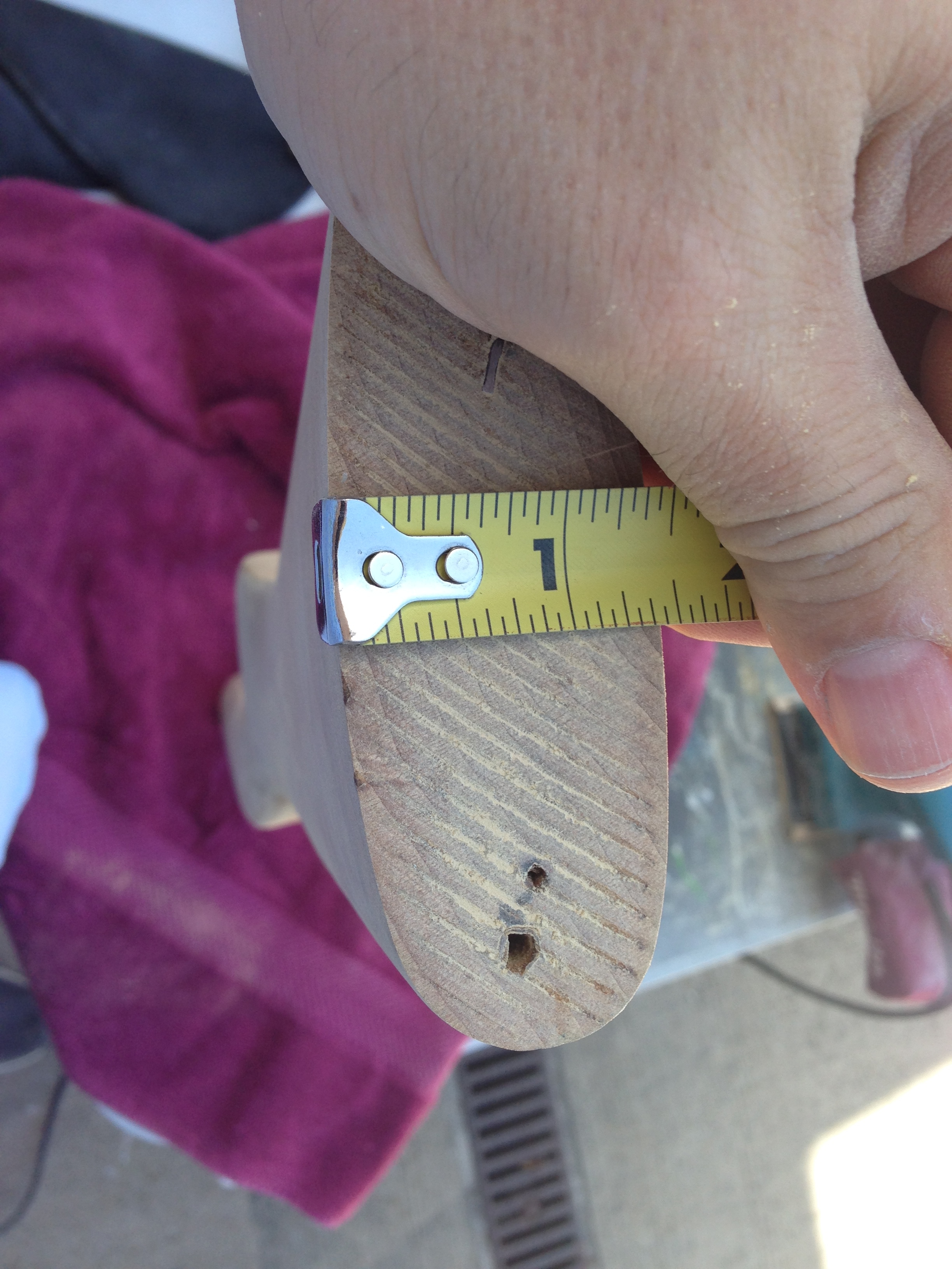
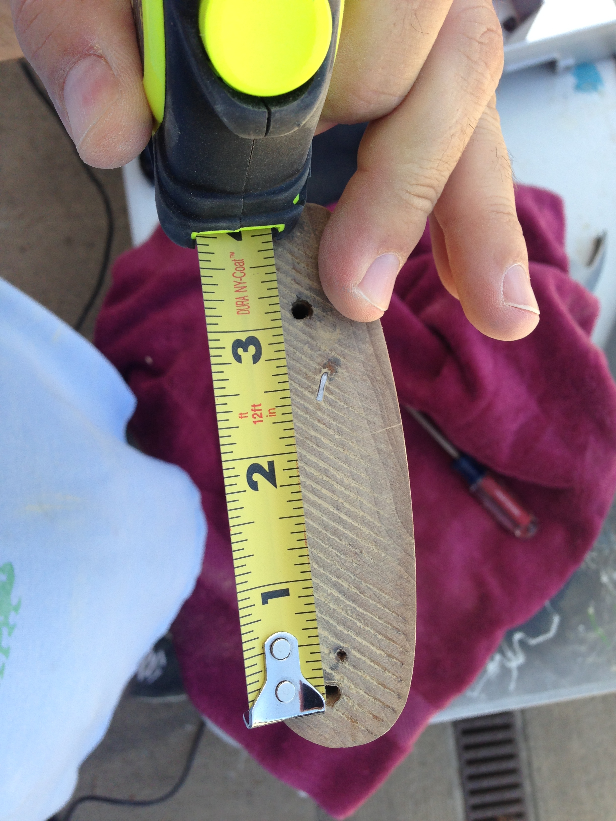
Dimensions are: Length 4.5 inches; 1 3/8 inches wide; from top of plate to mid of top screw hole 1/2 inch; middle of bottom screw hole to end of plate is 1 3/16 inches.

I think getting this on the butt of the stock is really gonna make this gun look great.
Fabricating and Painting Stencils
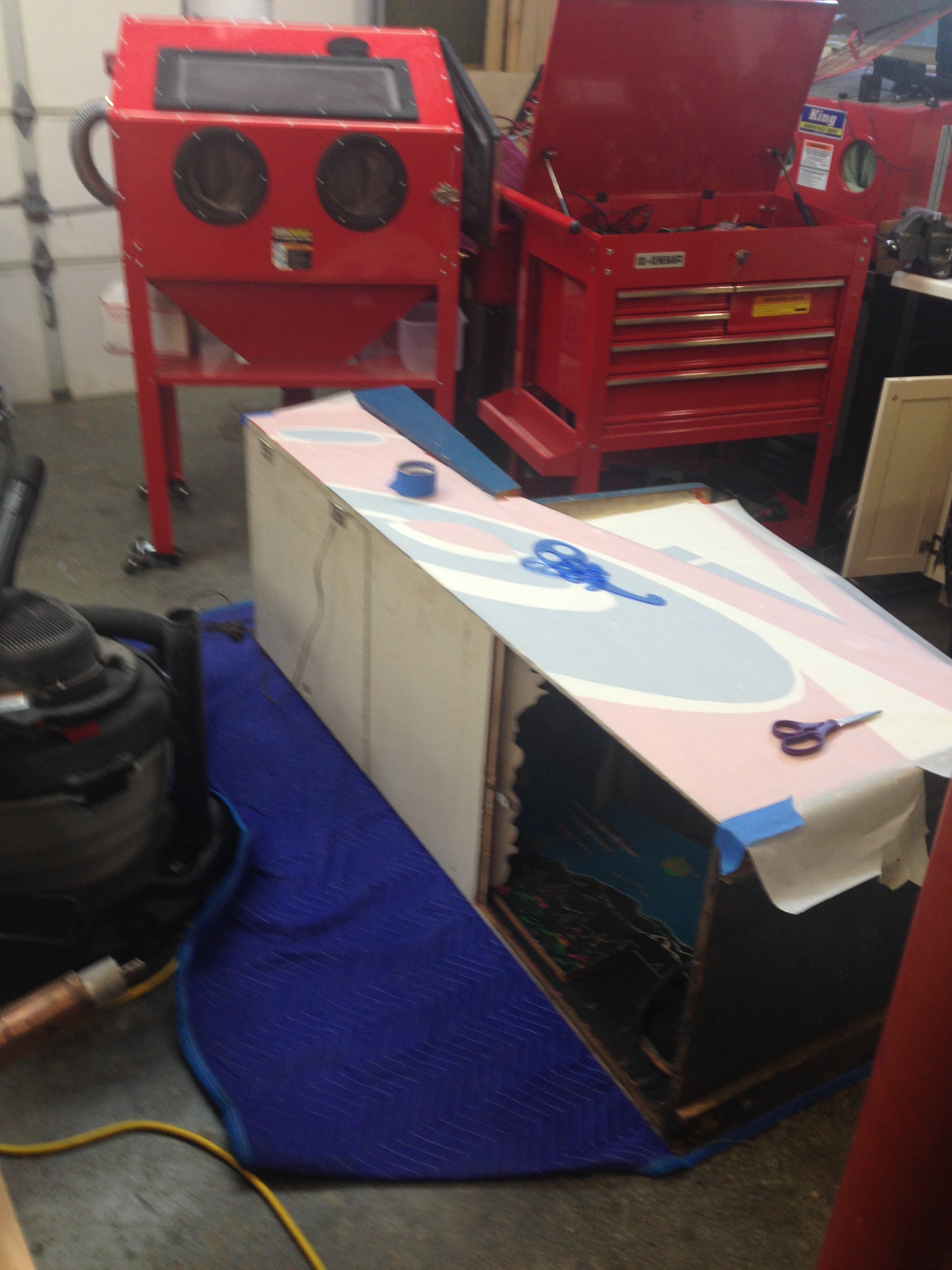
It’s been a while since I’ve either had time or been motivated to get back on this project. Part of the reason is that it’s time to make the stencils and paint them. This is my least favorite part, because I suck at this part, and it takes a lot of time, prep, patience, and planning to get this right. Stencils are hard to make, look horrible if you get them wrong, and take forever to paint, because typically I have to do one color at a time, as well as one side at a time. With the paint I’m using I typically have to wait a few days before I start the next color because it takes that long to dry to the point where it’s not tacky or still somewhat elastic.
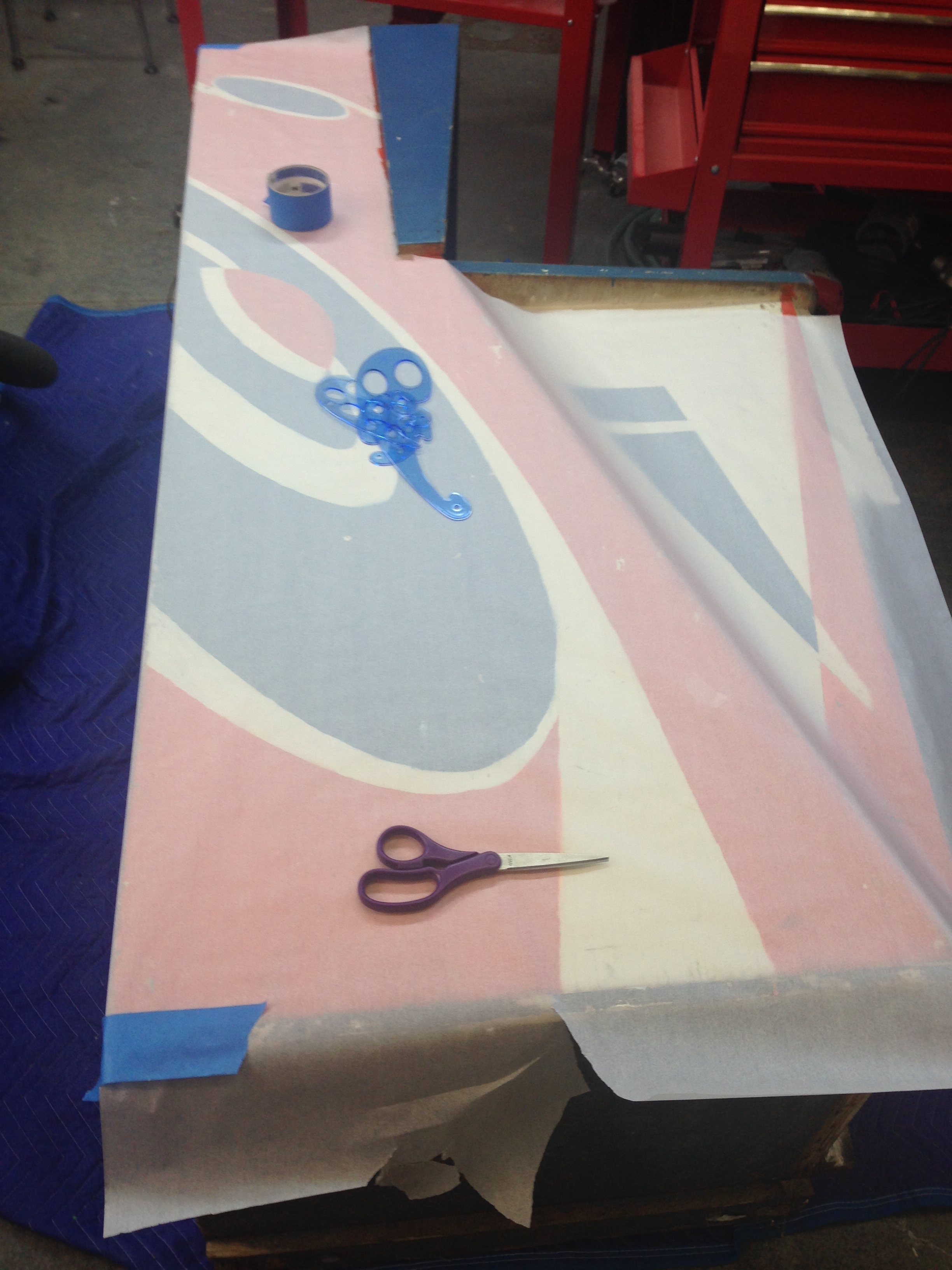
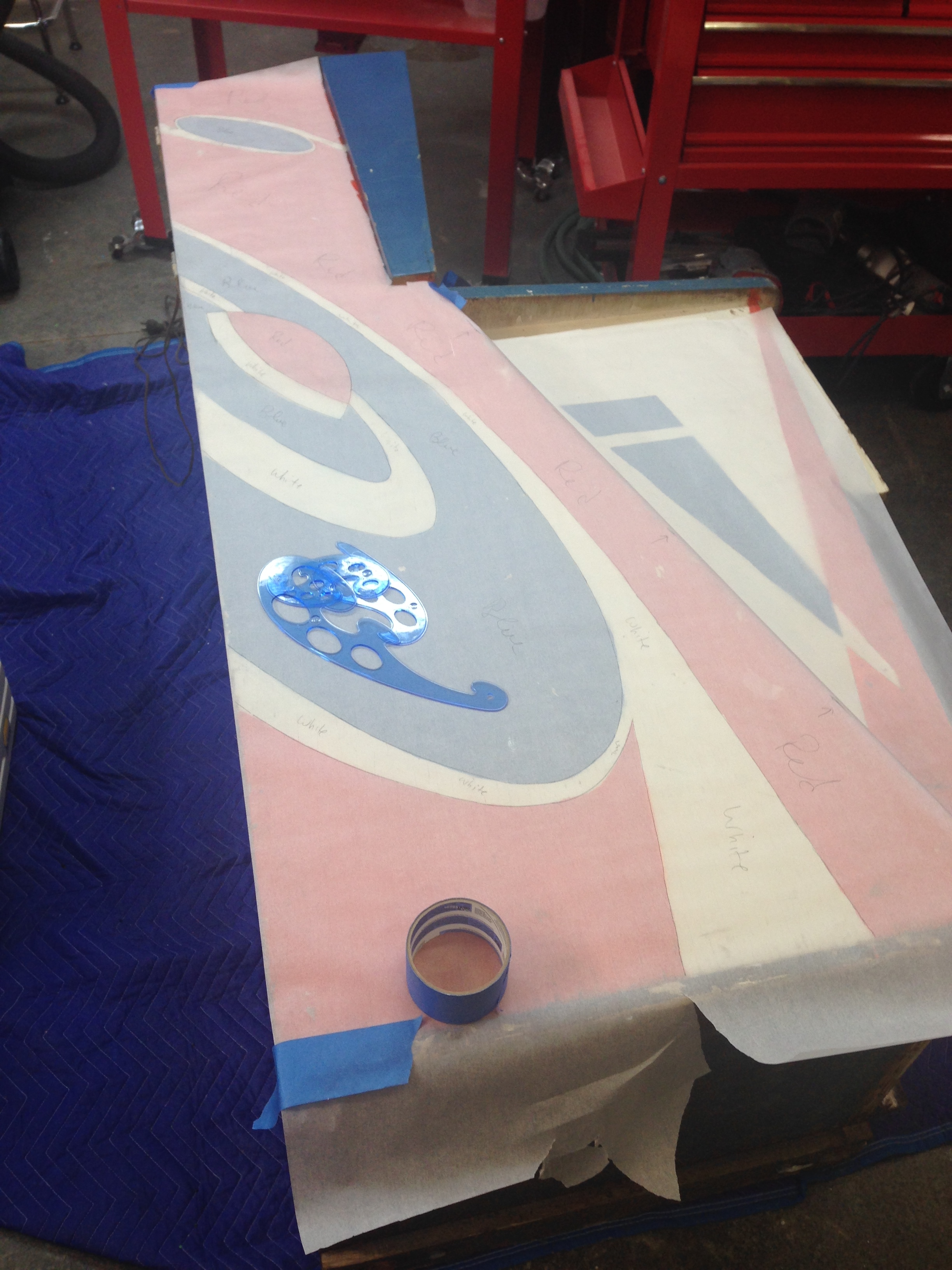
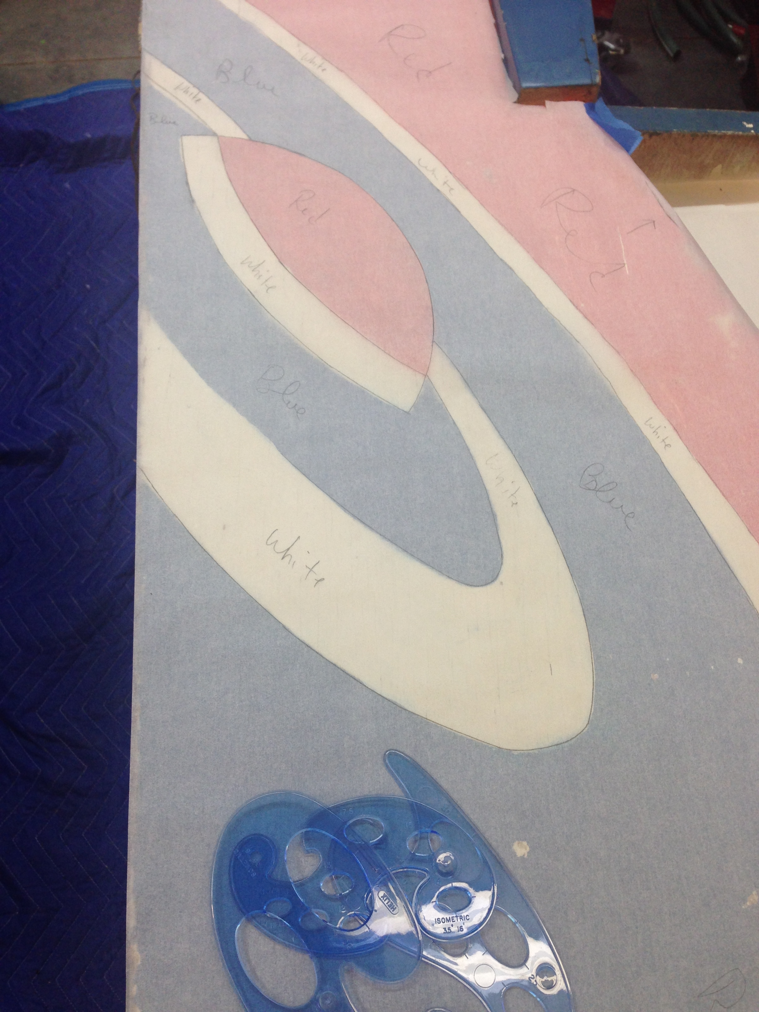
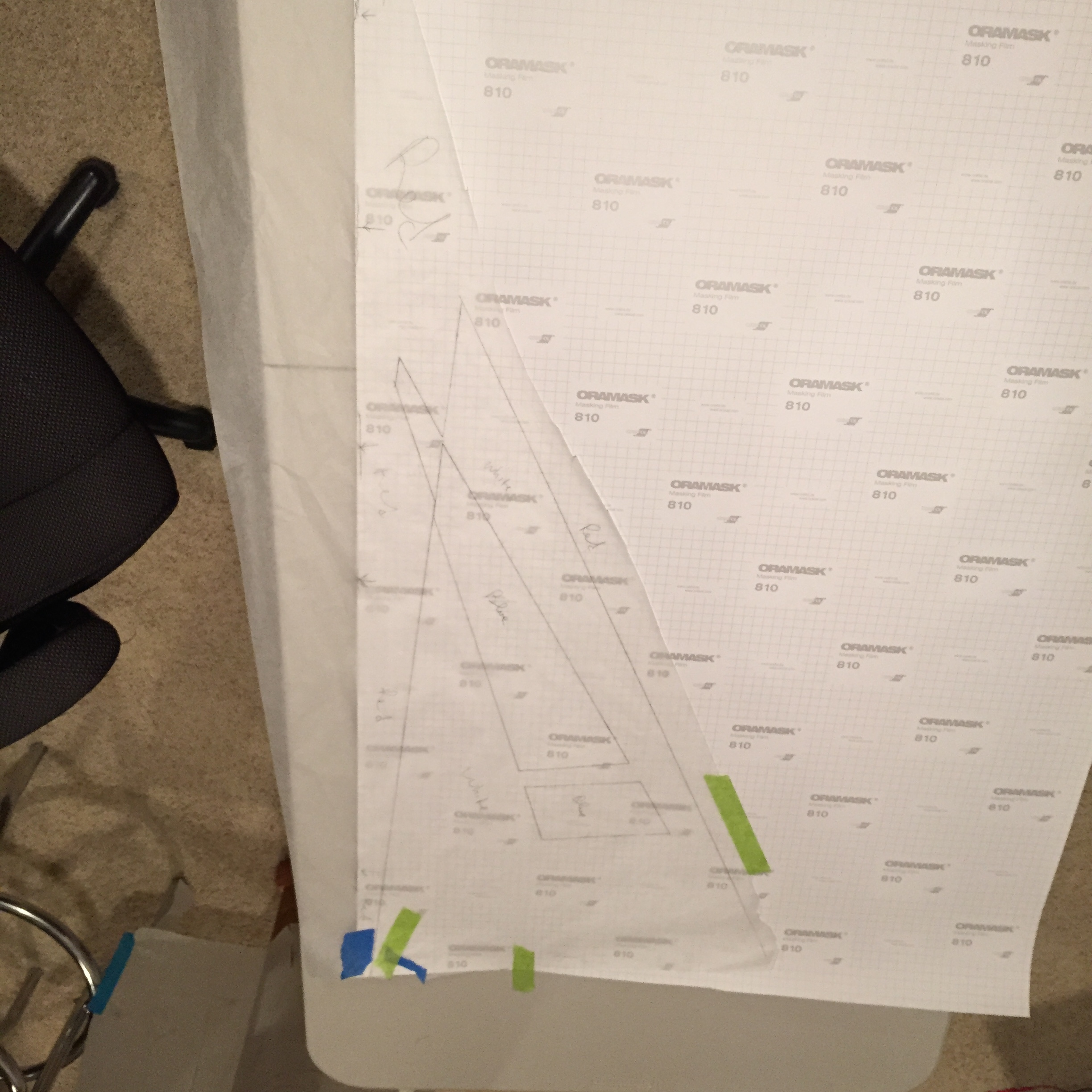
Anyway, I did get started on the stencils this weekend. I took the tracings I made a couple of months ago (before I stripped, sanded, and smoothed the cabinet), and used a sharp point to poke small pinholes through the tracing paper into the the siliconized stencil paper I mentioned above.
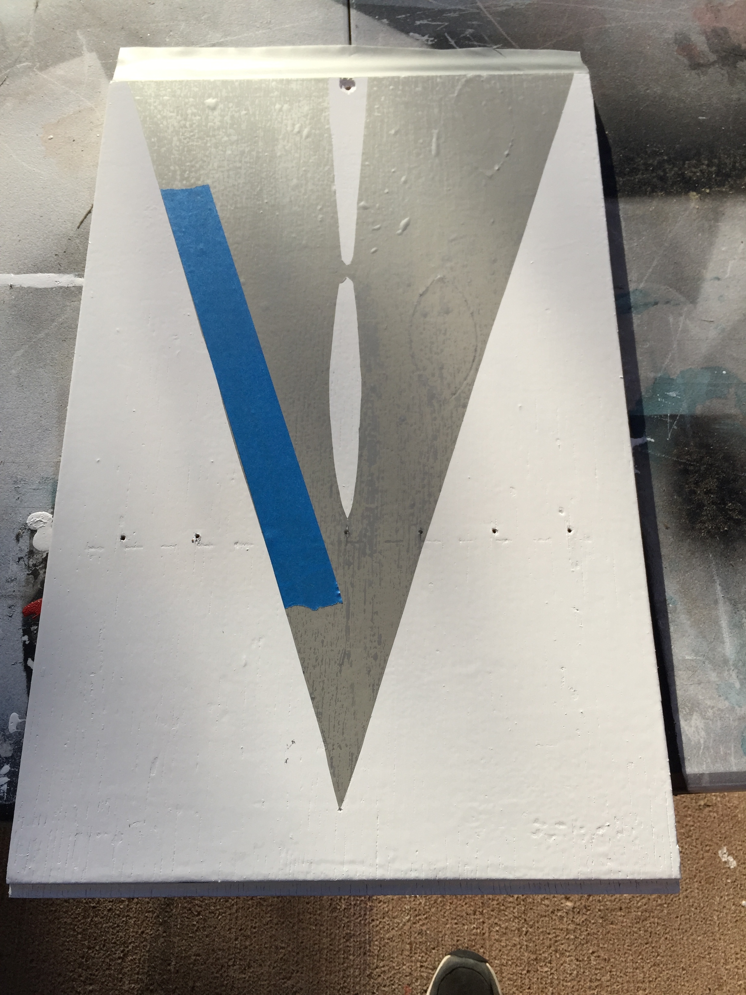
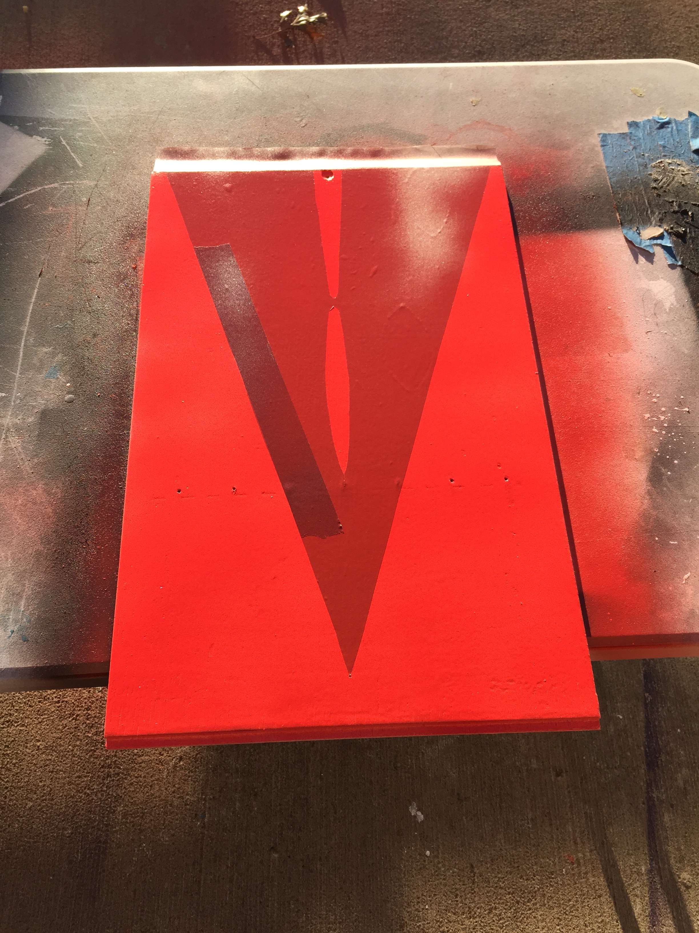
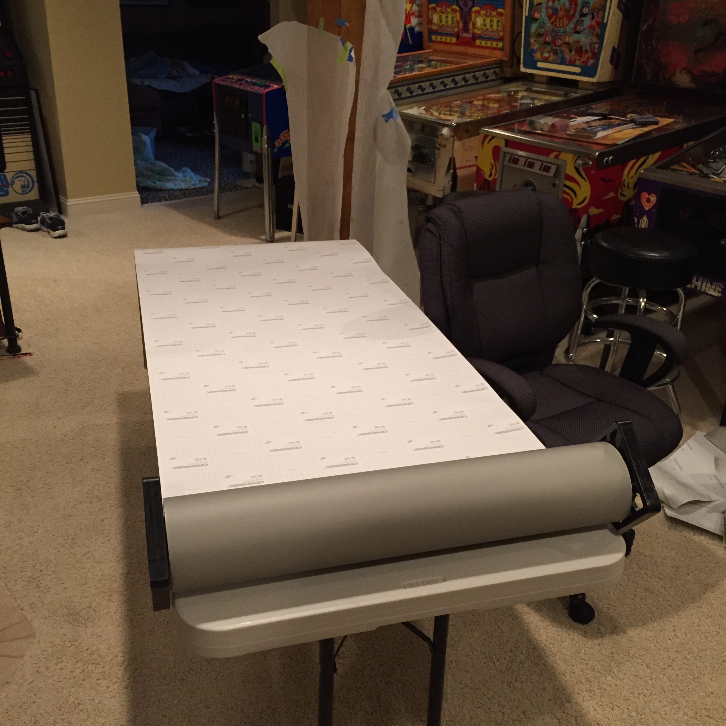 I started by rolling out the stencil paper on to a long smooth table, and cutting it a little longer than I needed. I then laid my tracing paper over it, positioned it, and taped them both down to hold them in place while I worked on it. I decided what colors I would do in which order, and then did the stencils in that order. For this game, I needed a white base coat (partly because the other colors needed a white base coat to look right). I then took my sharp pointy instrument, and poked small holes around the edges of my first color (red). Then I took off the tracing paper and cut out the red holes. I then moved on to make the stencils for the blue color following the same process.
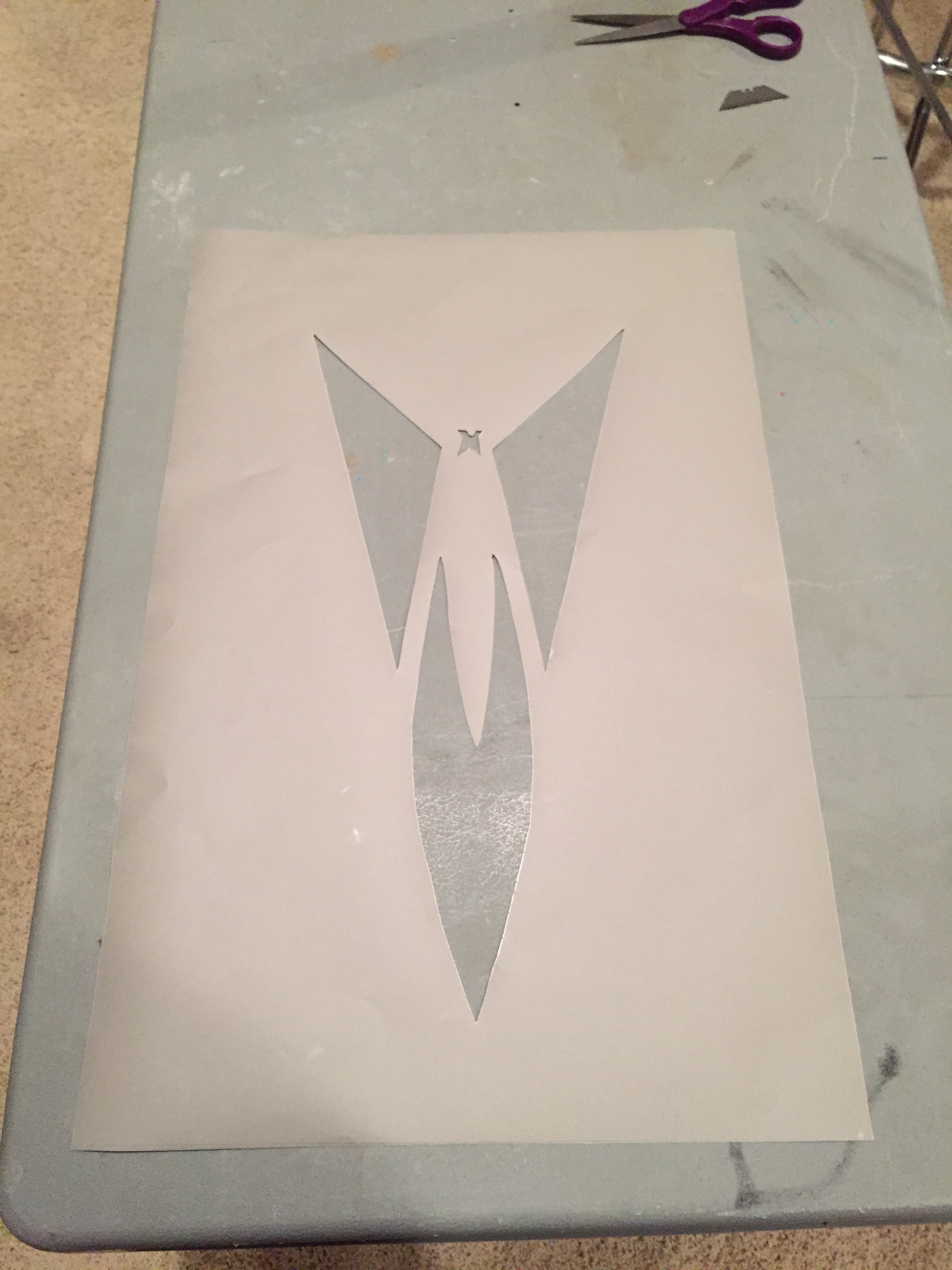
 Once the holes are cut, the stencil is ready to be used.
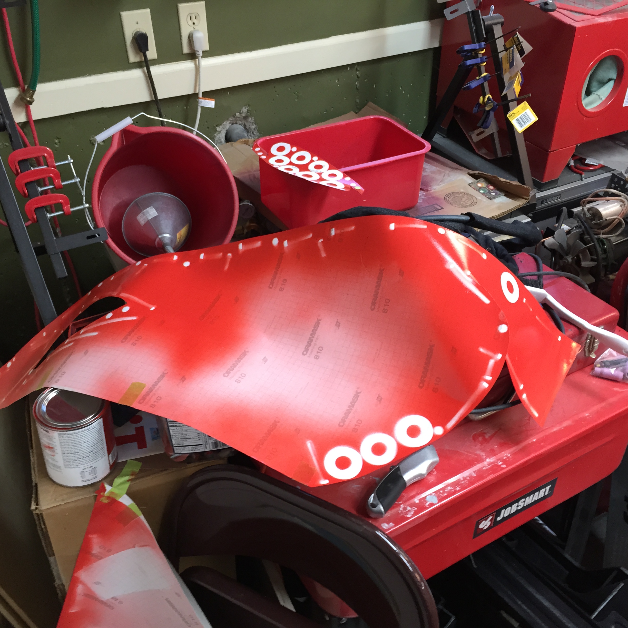
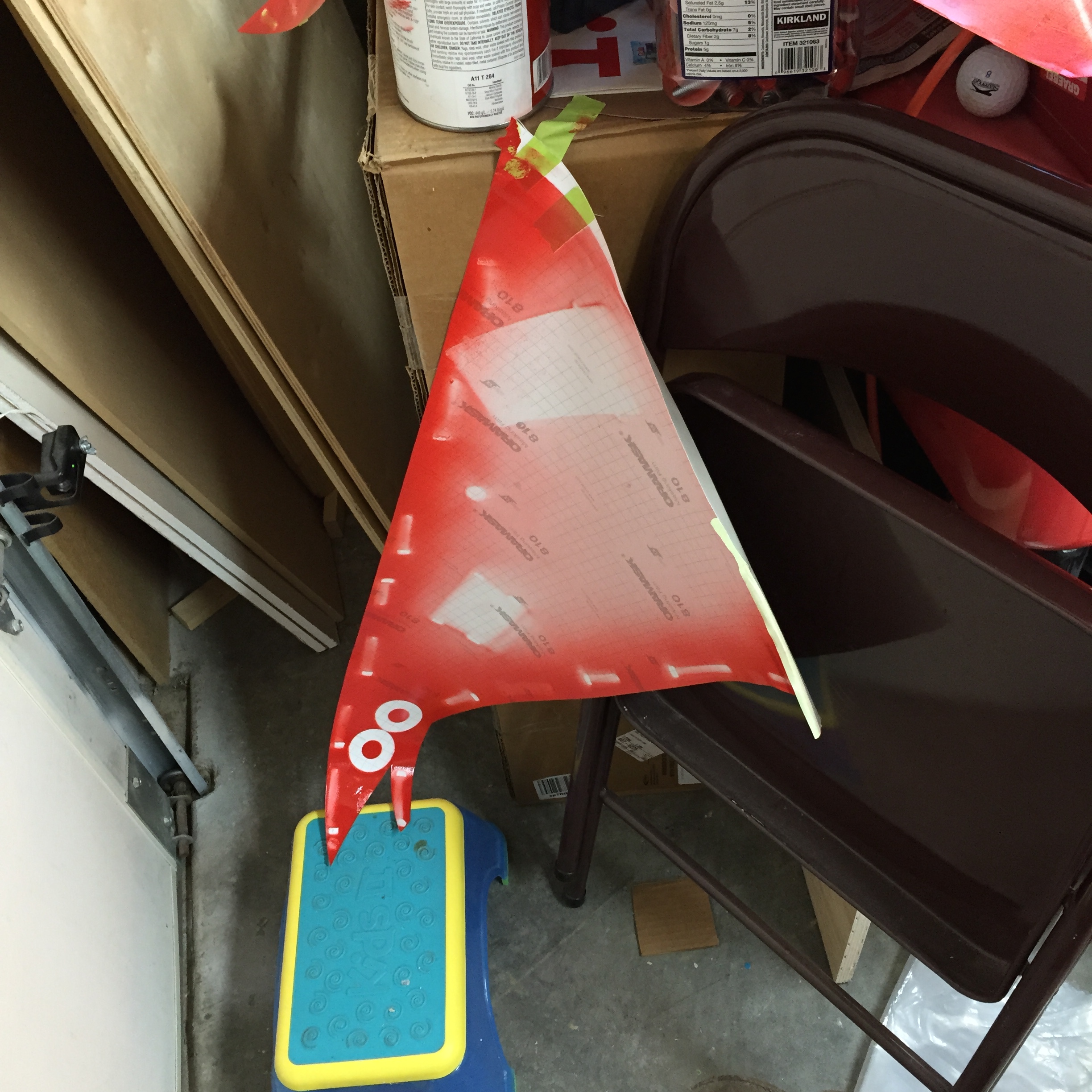
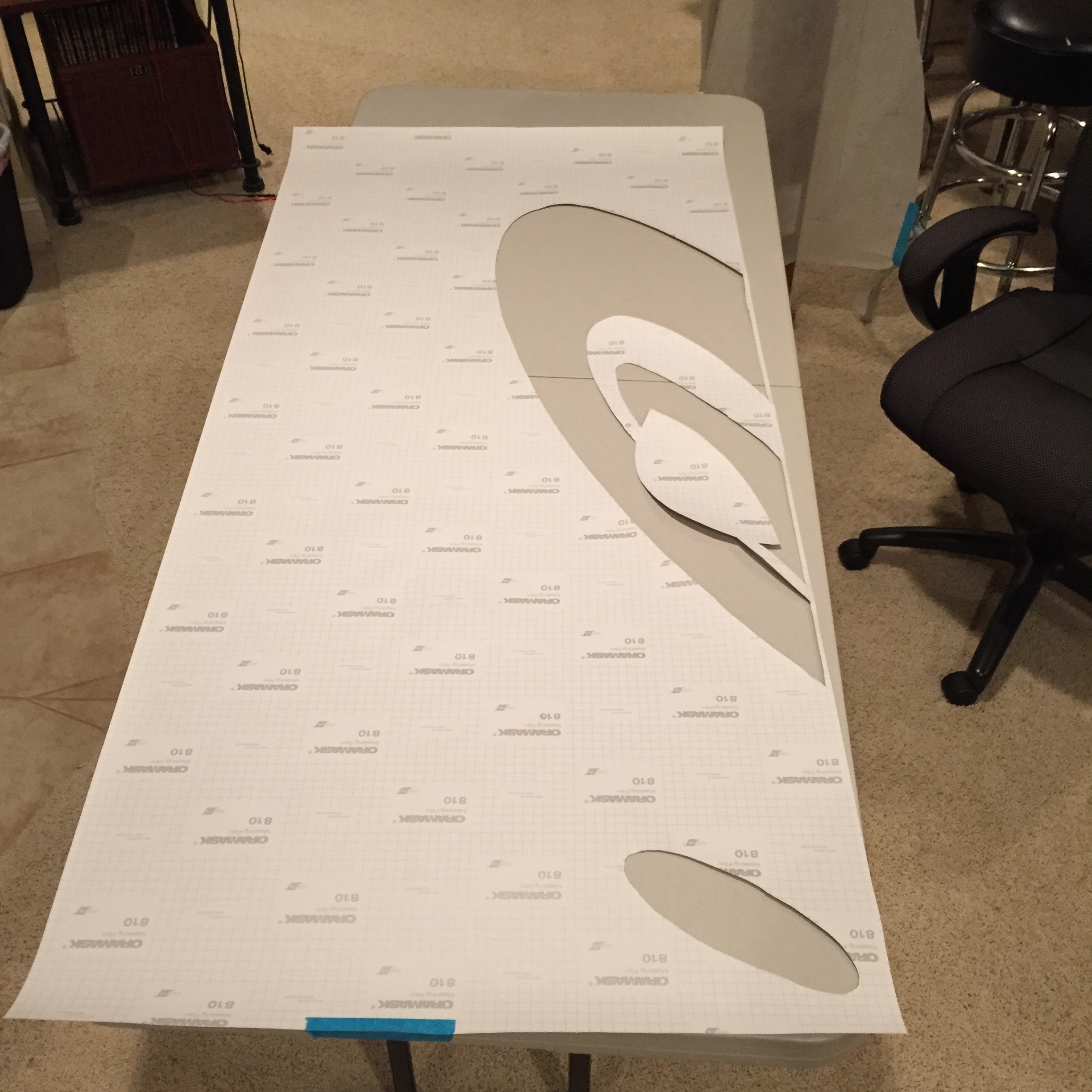 Here’s what it looks like once it’s cut. This material is slightly adhesive if you peel it off the backing. Since I’m going for a more original look with some slight overspray I’m just laying the stencil material on the cabinet (flat), and weighting it down to hold it in place (around each of the holes).
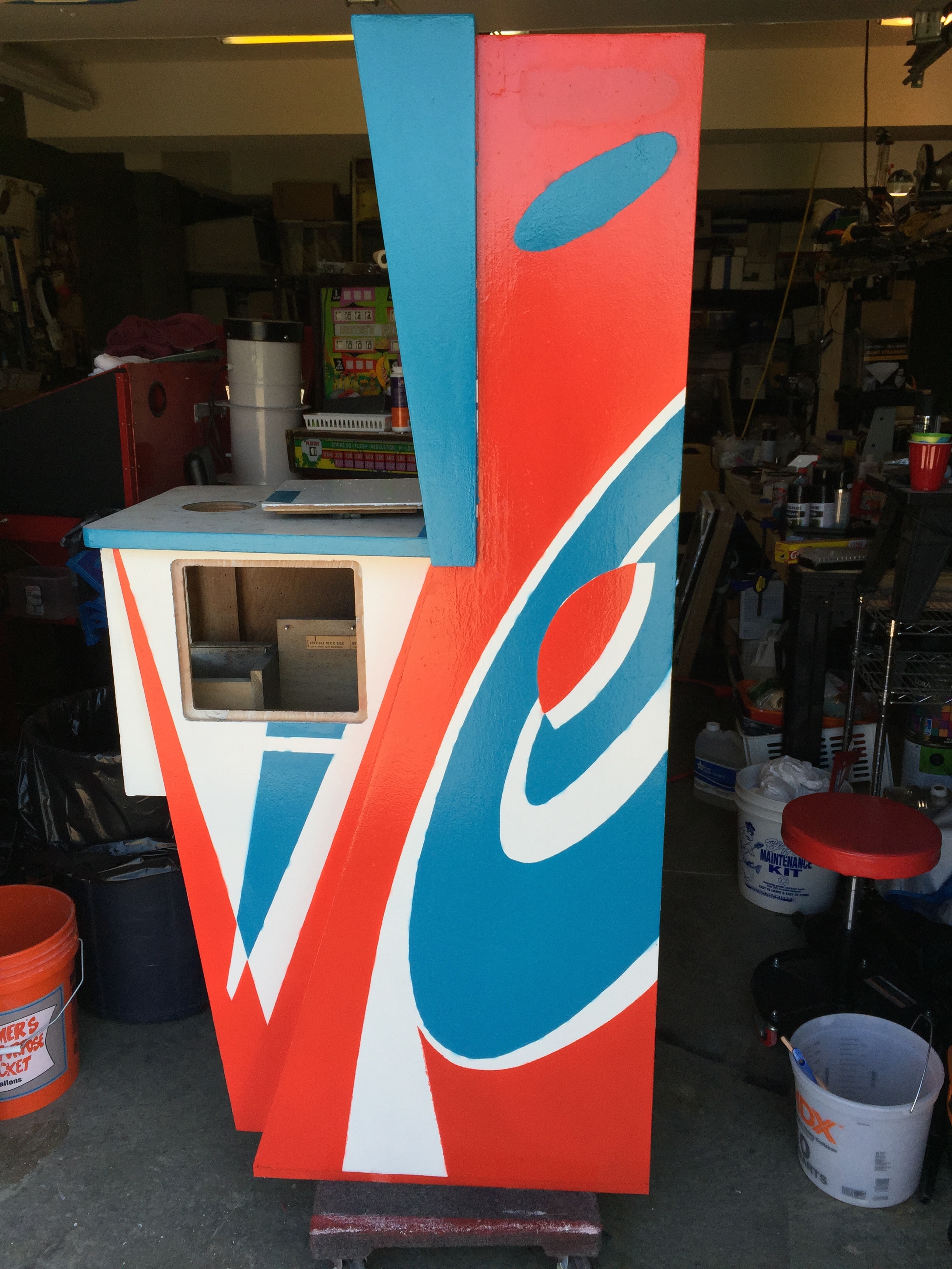
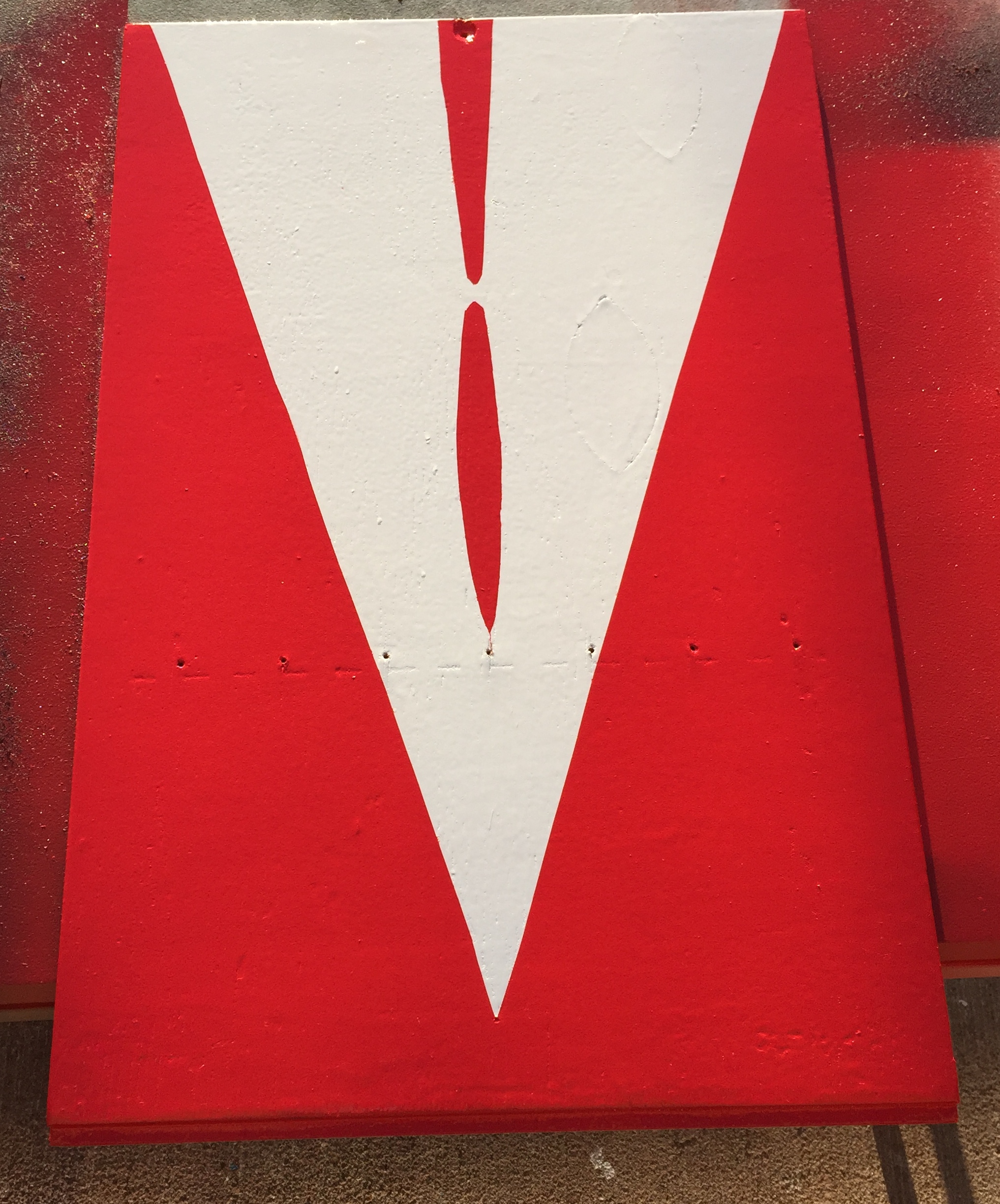
I’ve got the red painted on one side only at this point… here’s what it looks like so far.
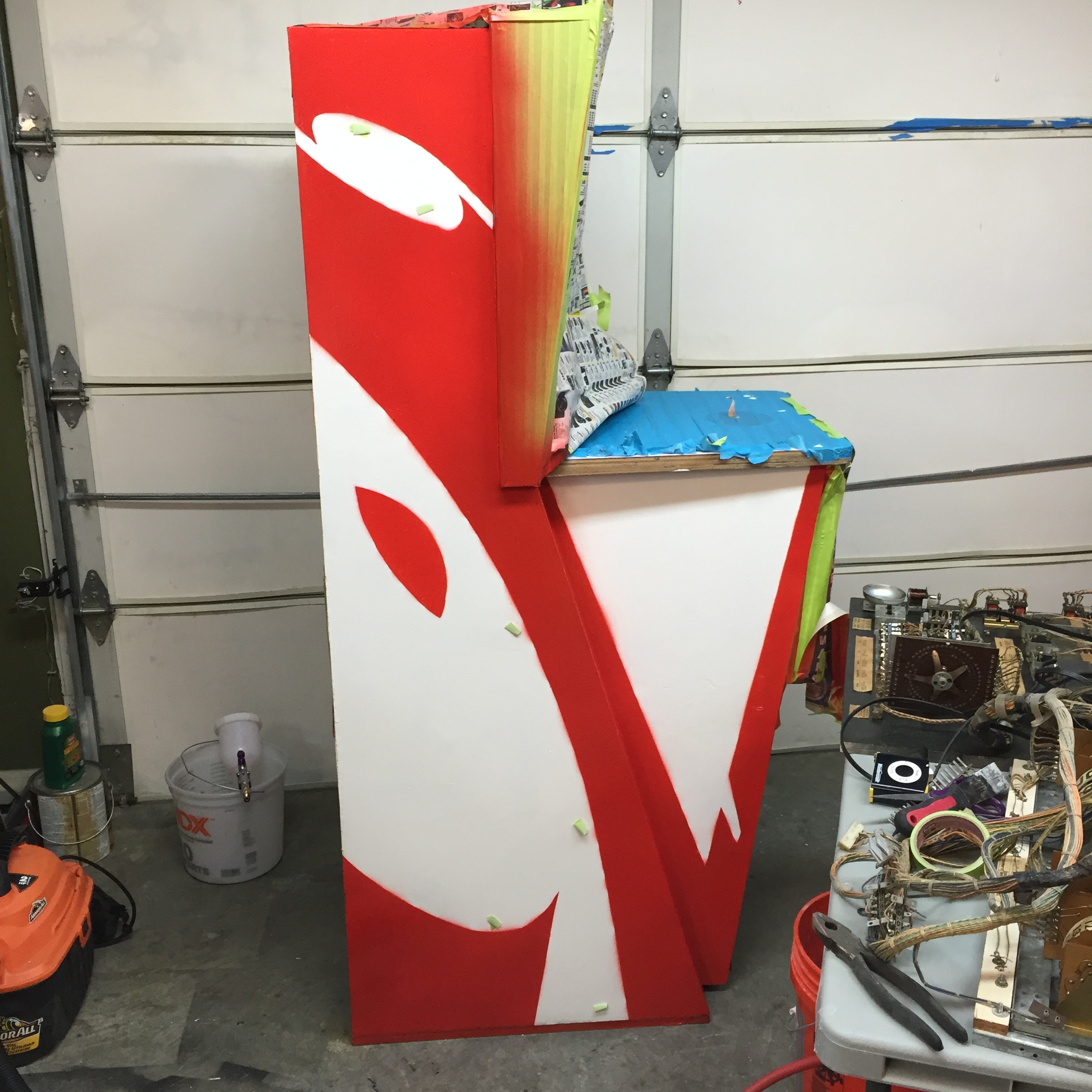
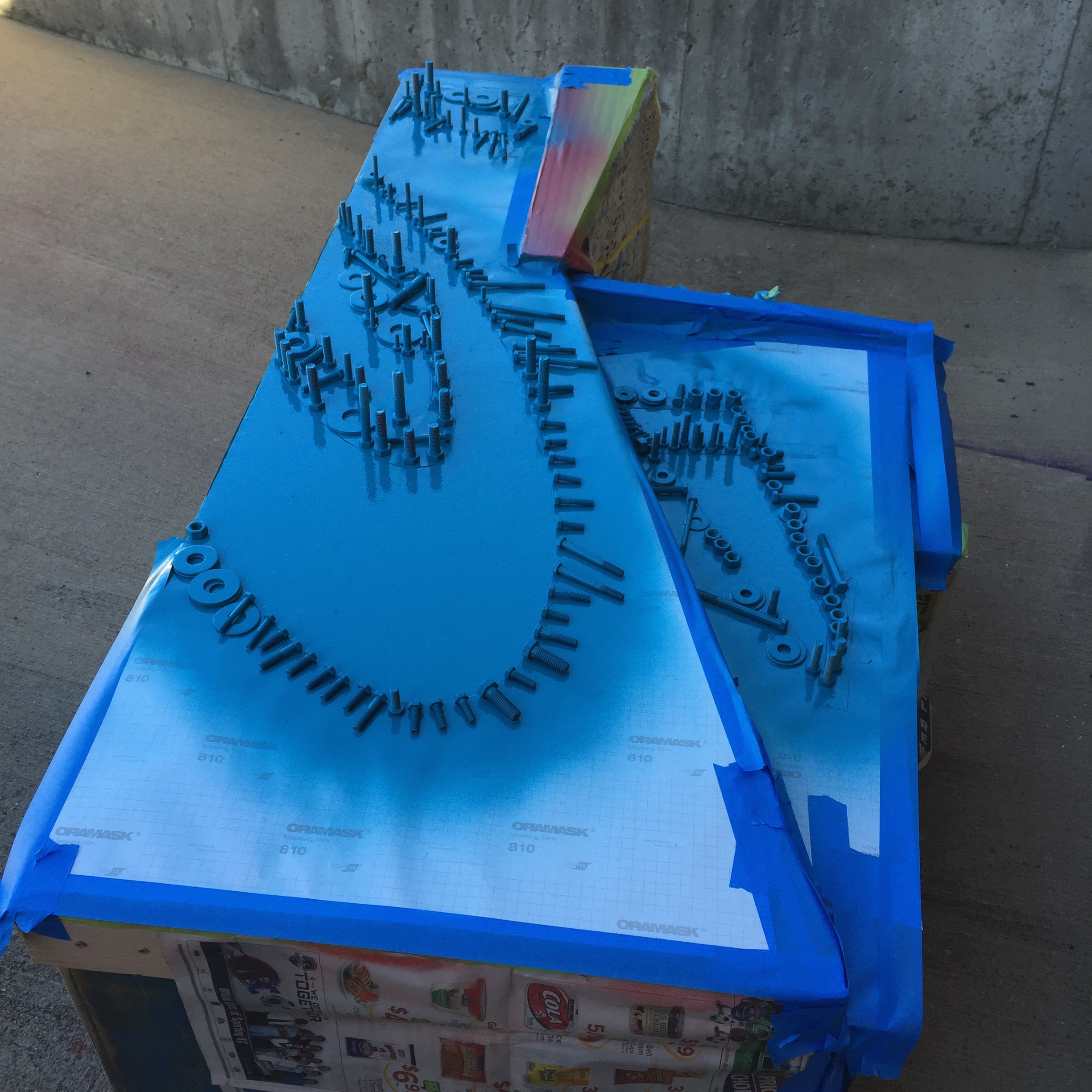
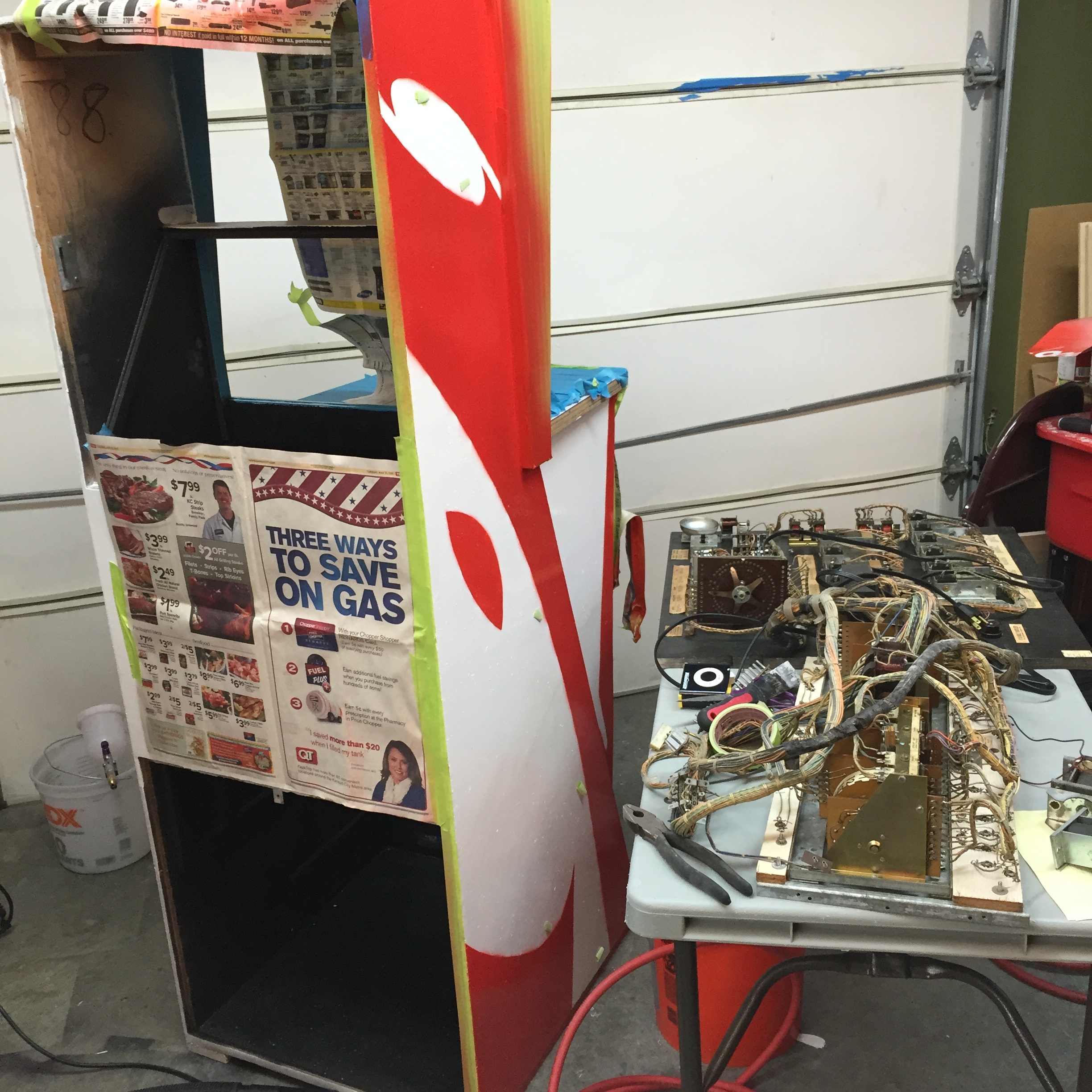 I painted this flat (the stencil stays in place better and you can weigh it down), but stood it up for the picture. I used a bunch of big bolts and washers I had to weight down the stencil and I placed them all around the edges of all the holes/edges I was painting. I had the air pressure up too high on my HVLP gun when I got started and it was blowing so hard it was getting under the stencil material and lifting it up (even with heavy bolts laying on top of it). I lowered the pressure and got a better spray, and it was low enough I didn’t have that problem any more. If I had anticipated this I would have done some testing with this stencil material in advance… as it stands, this side will not be quite as nice as I would like, but it still looks quite passable I think. You can still see a few pieces of green painting tape I used to hold the stencil in place, just not removed yet. Here’s what the cut stencils look like. I’ll flip these over and use them to paint the other side once the paint is completely dry on both the side I’ve already painted and the stencil as well….
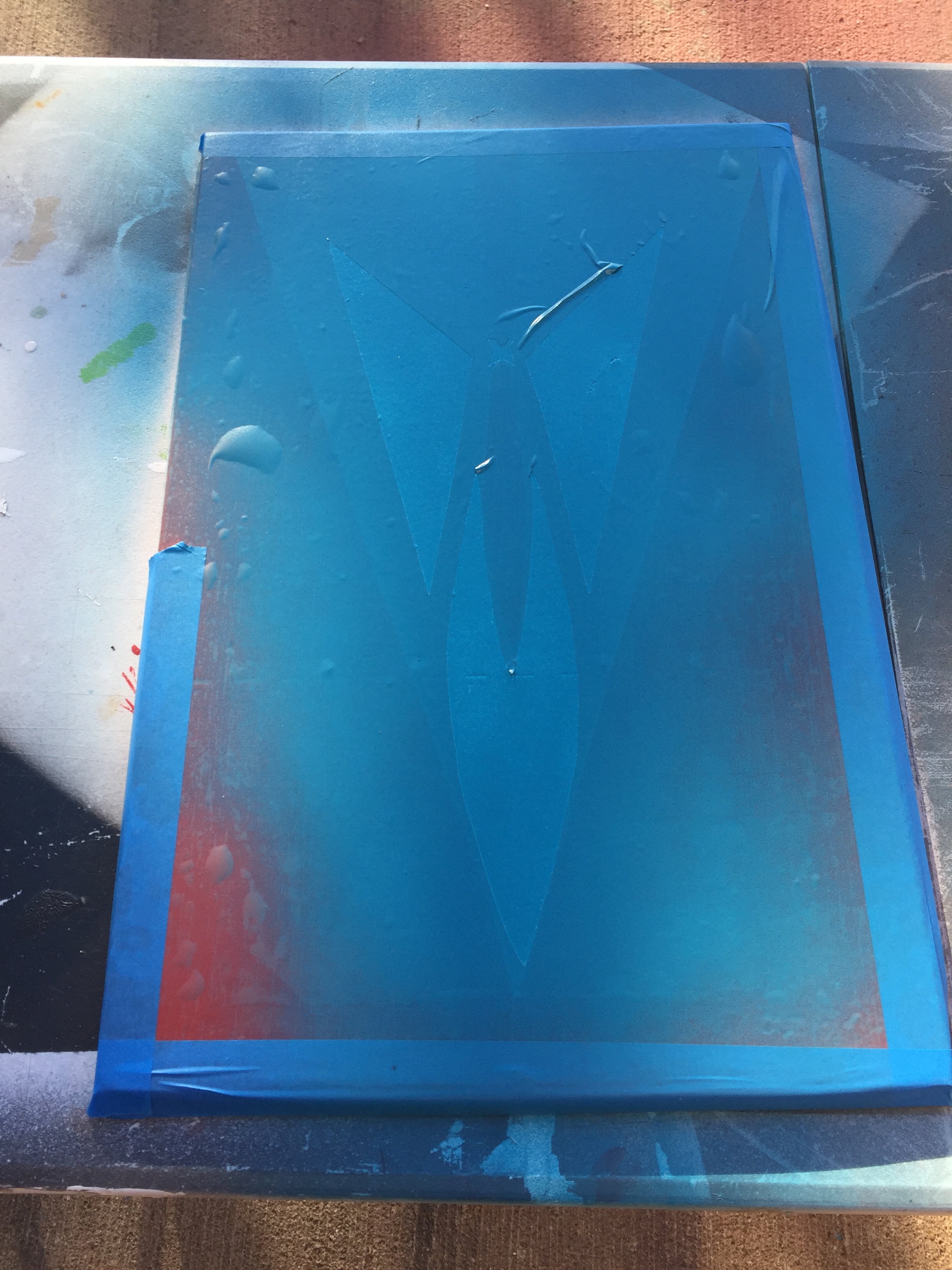
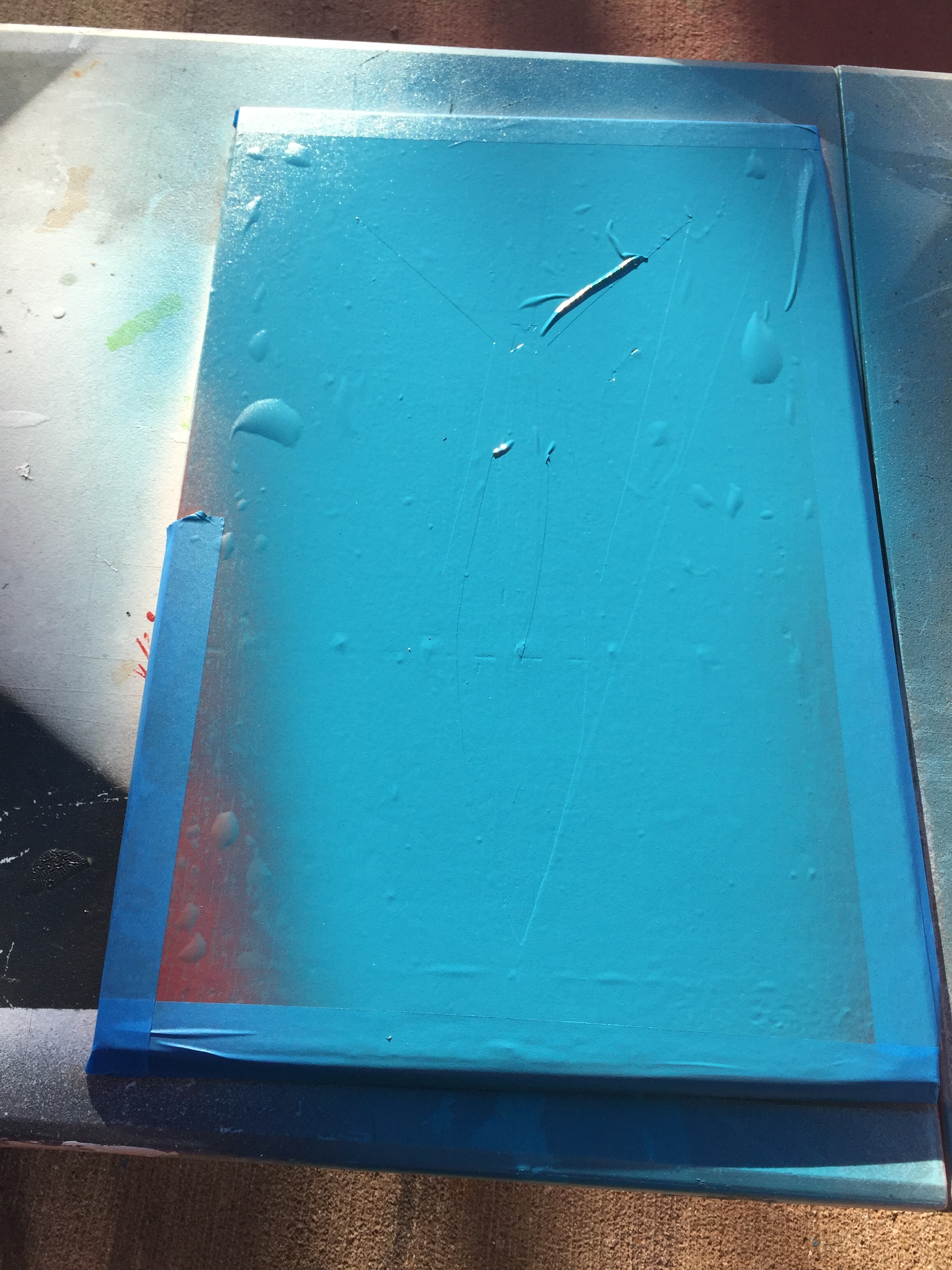
I did the blue stencils the next day. I sprayed it just a little too thick before letting it set up and got a few areas where the overspray was more than I wanted, in addition to a few places where the paint puddled under the edge of the stencil. These are pretty easy to clean up using a little Novus 2 and some rubbing… Here’s a few more pictures of painting stencils, and what the side looks like finished.
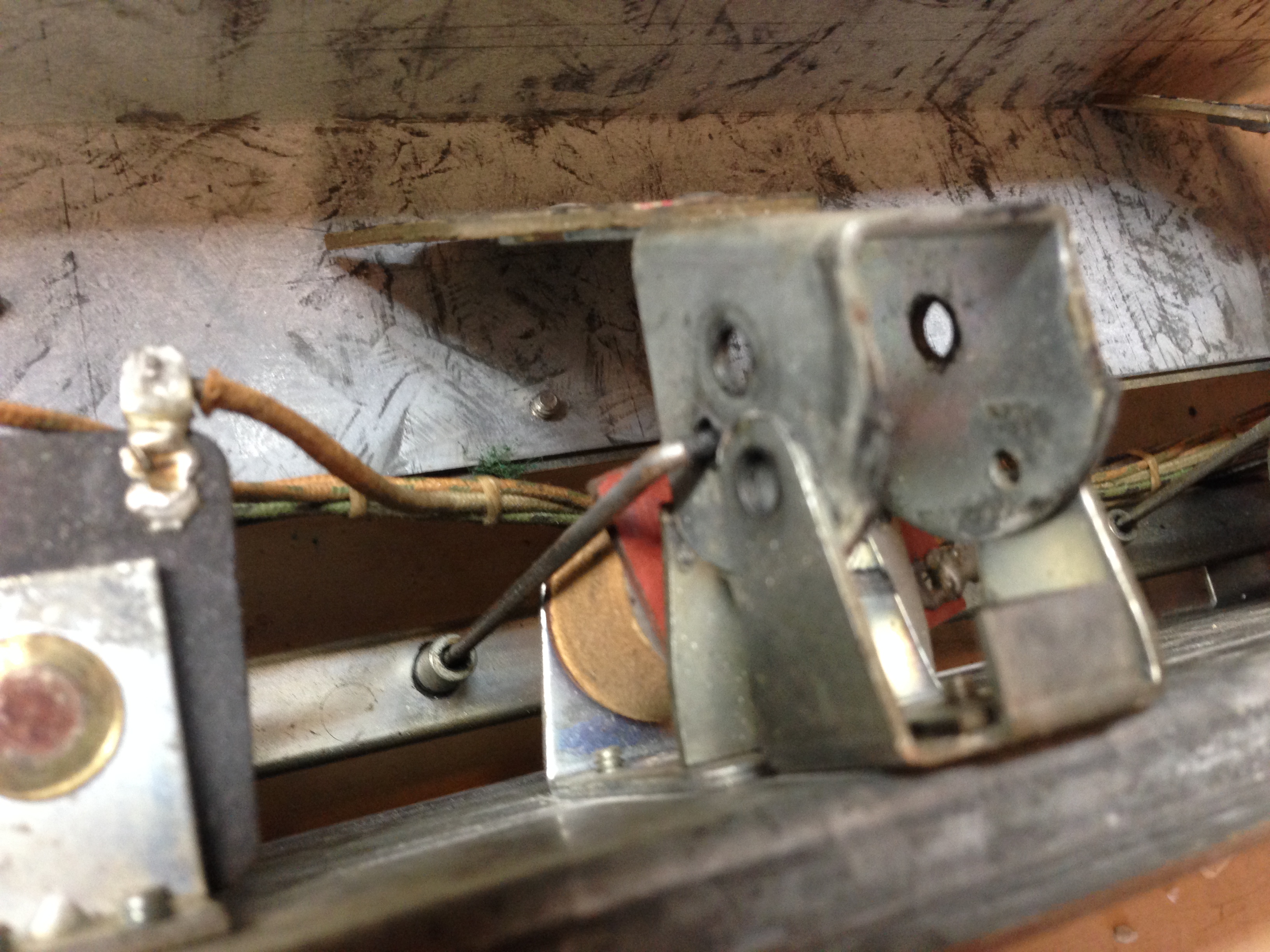
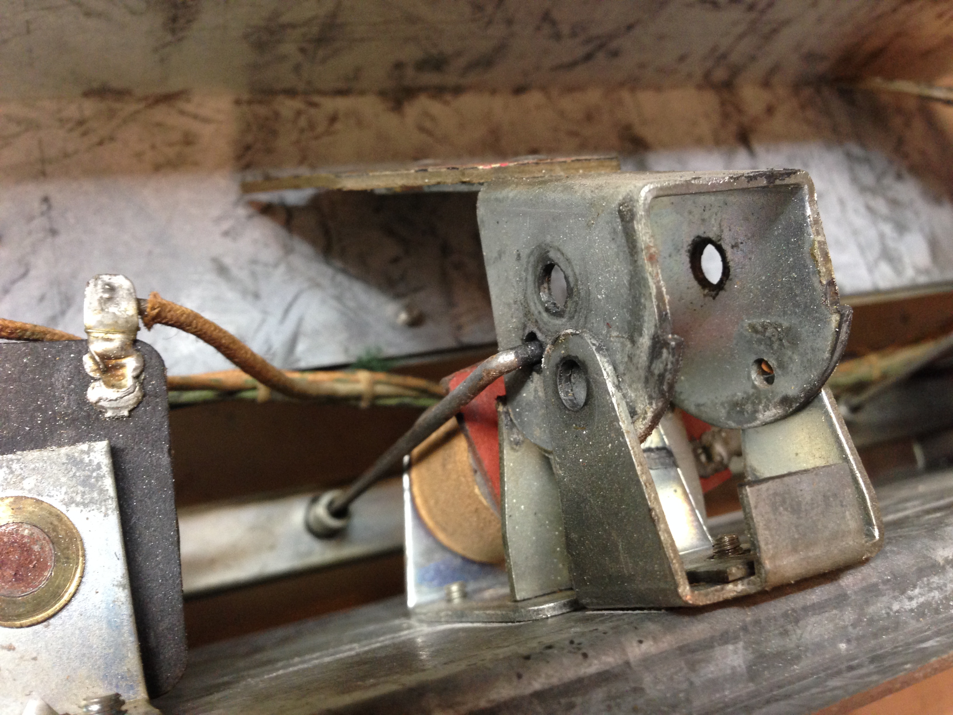
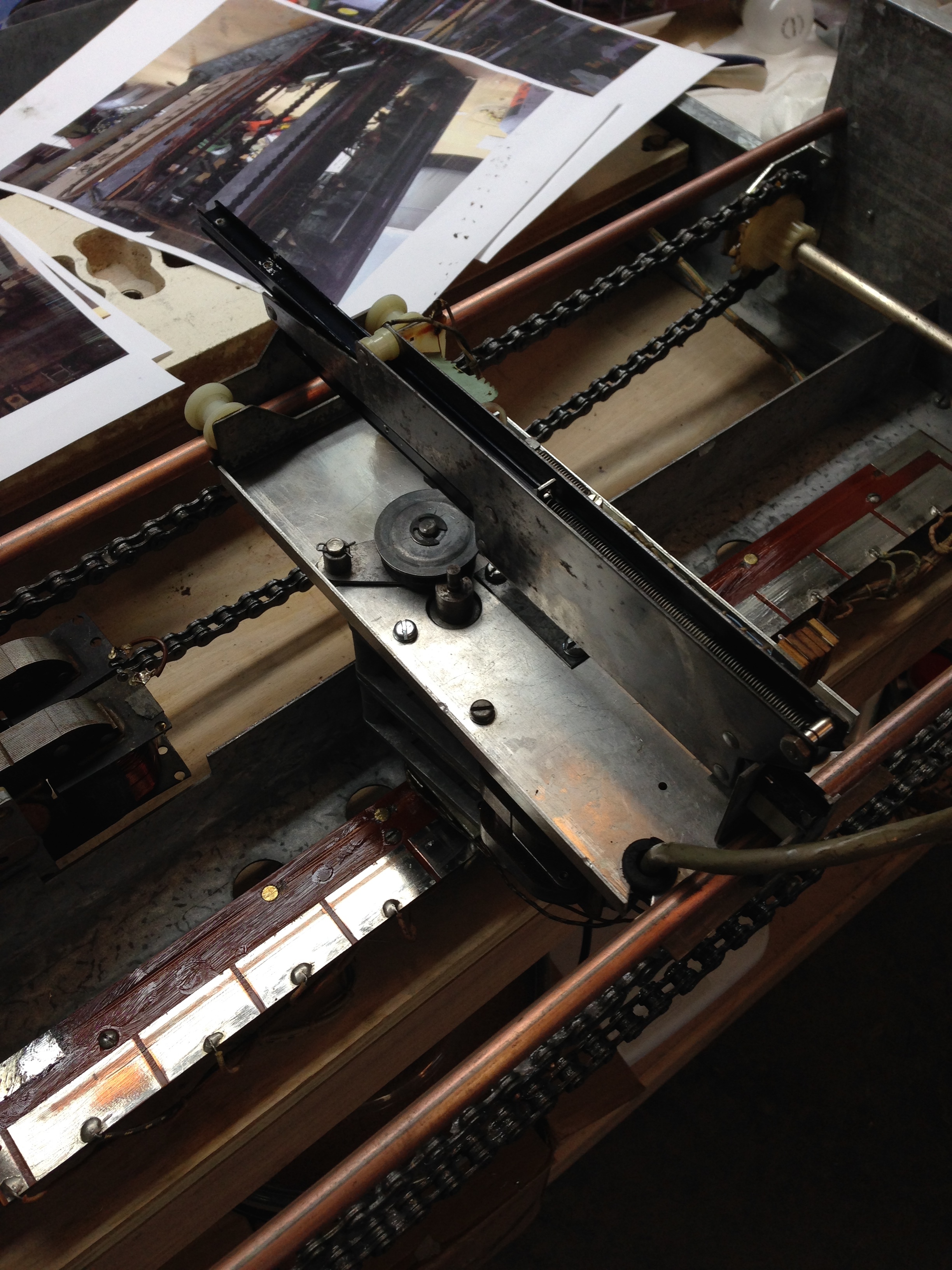
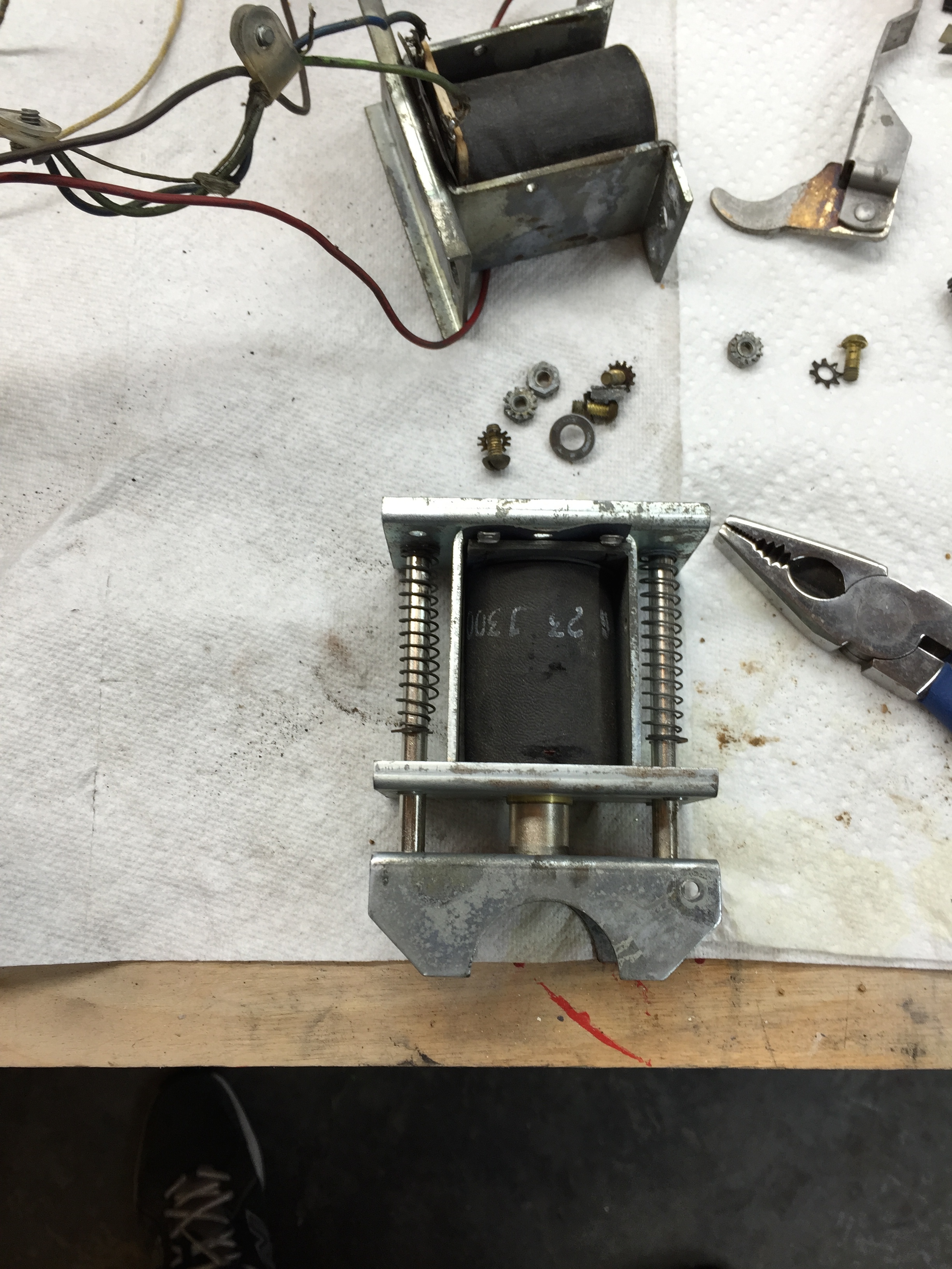
Reassembling the Gun Assembly
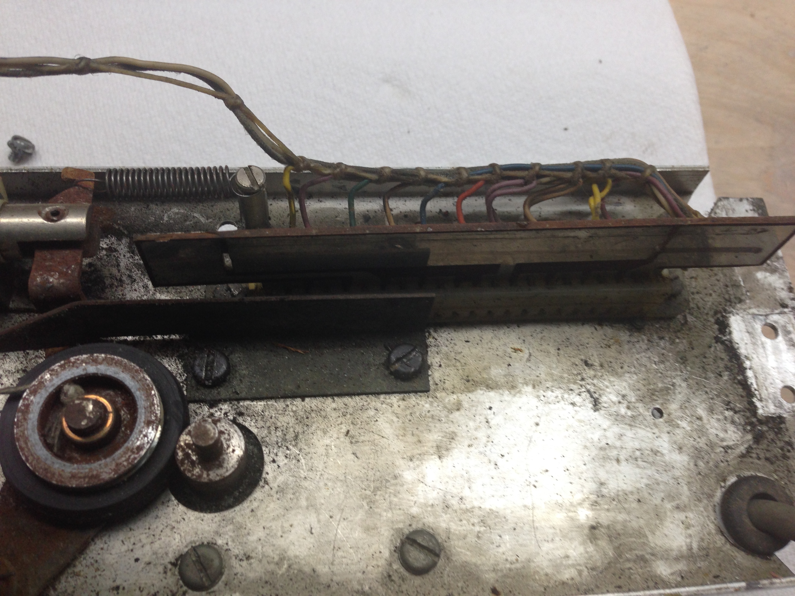
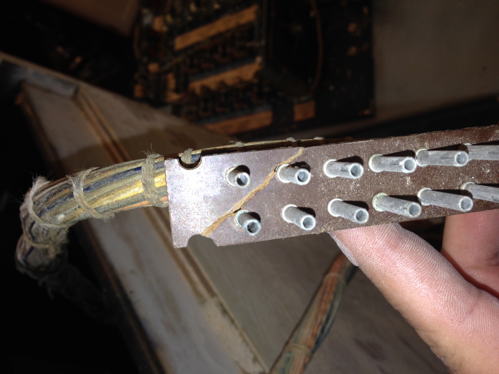
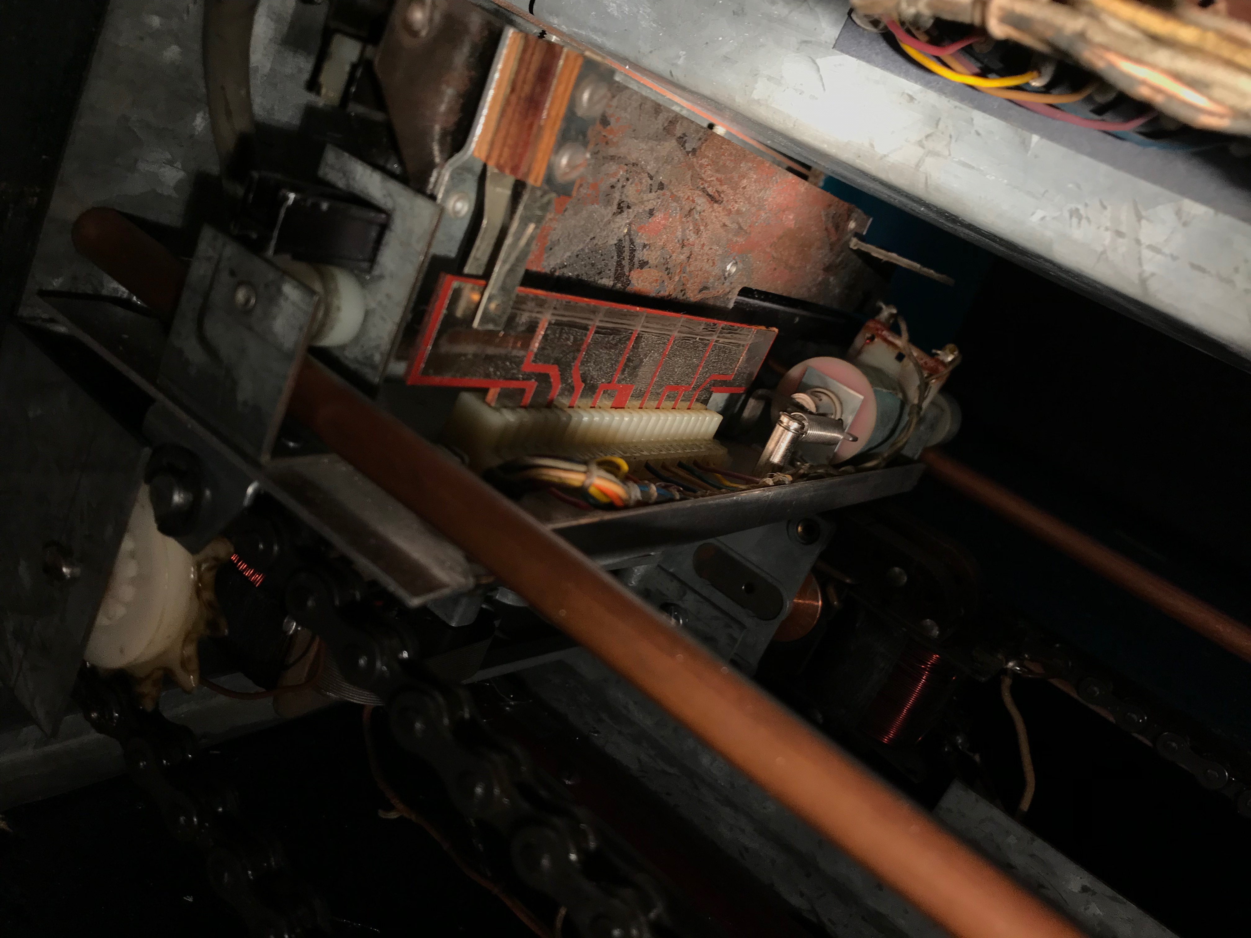
Now that the cabinet paint is done it’s time to get this thing put back together. I’m not sure why, but I started with the gun assembly. I was kinda dreading this as I think the problems with the gun assembly was why this particular game had died and ended up in a warehouse for many years. If you recall one of the “stylus” arms was bent and broken. The brass stylus tips that slide along the printed circuit boards to register where your gun is pointing were in really tough shape. The fiber board that holds the brass channel that the stylus’s slide up and down in where both in tough shape, lose, cracked and superglued. The brass parts were worn and bent. The printed circuit board was worn to the point where there was a groove in the fiber material. I believe this, in part, is what lead to things not working right, and eventually to the failure of the stylus arm.
I started to gently flow some super glue in the worn parts of the printed circuit board thinking that this would make a smooth surface for the stylus arm to ride on, but then I started worrying that it would just wear quickly through the dried super glue. Then I thought if I just drilled a couple of new holes in the circuit board, I could just move it over about 1/8″ and the stylus arm would have a fresh surface to ride on. Here’s some pictures to illustrate what I’m talking about.
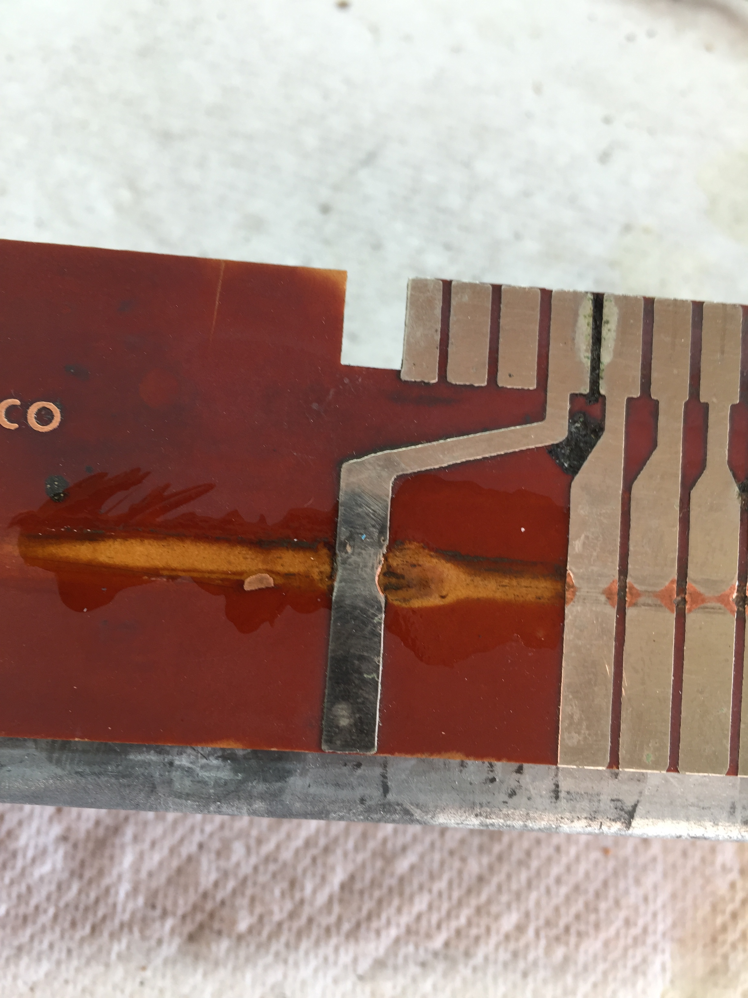
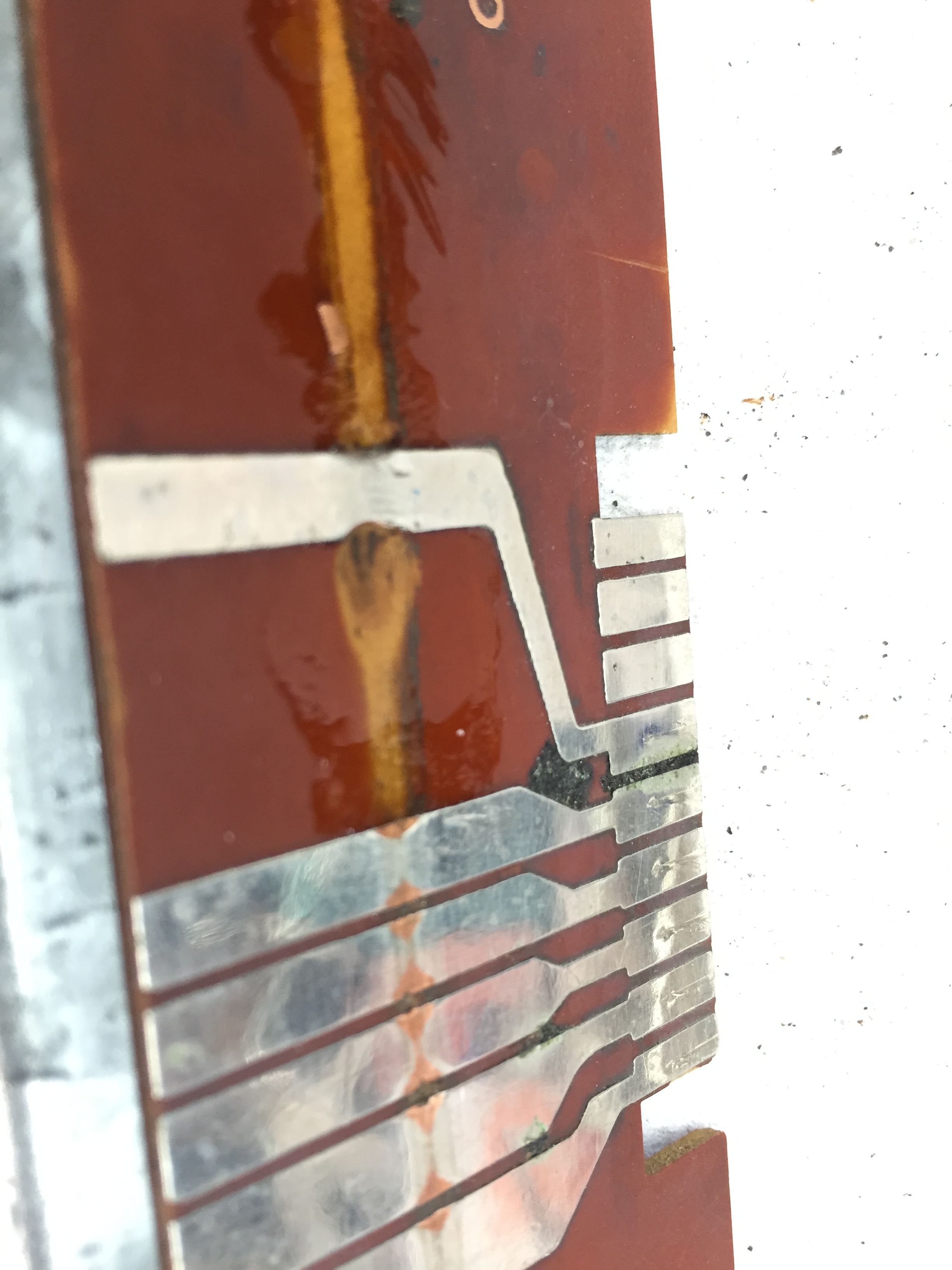
You can see in these pictures just how worn that one particular area is! The stylus needle was catching on the trace each time it tried to slide across, even with a thin layer of teflon gel lube. You can see the super glue I added to smooth it out. Here’s what it looks like now with the new holes and remounted over about 1/8″.
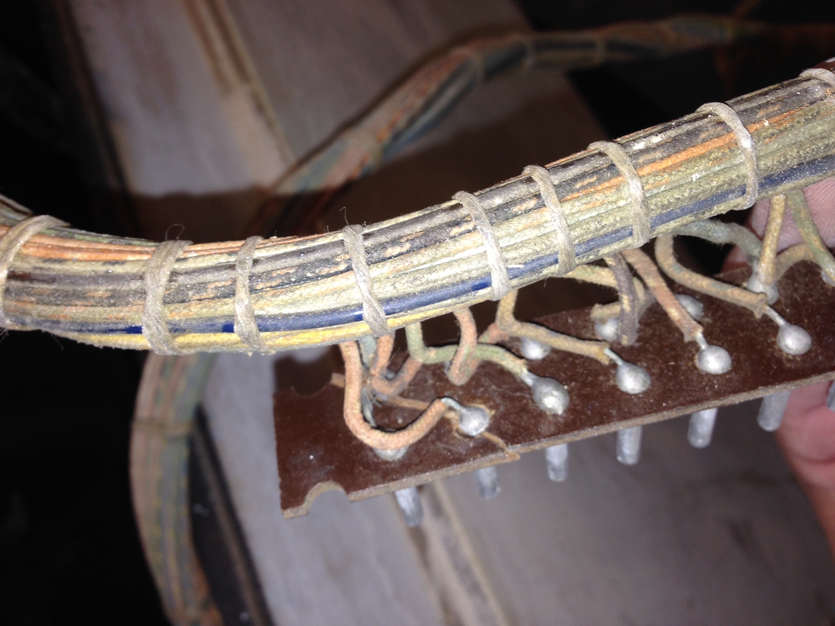
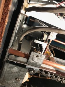
I had purchased a new coil assembly for the gun recoil coil, as the brass coil sleeve was worn through on the old one. I had to re-solder the connections to the coil, re-mount it to the gun, and then run the wires for the trigger switch back up through the gun mount. I used a piece of piano wire as a fish tape to thread the wires up through the mount.
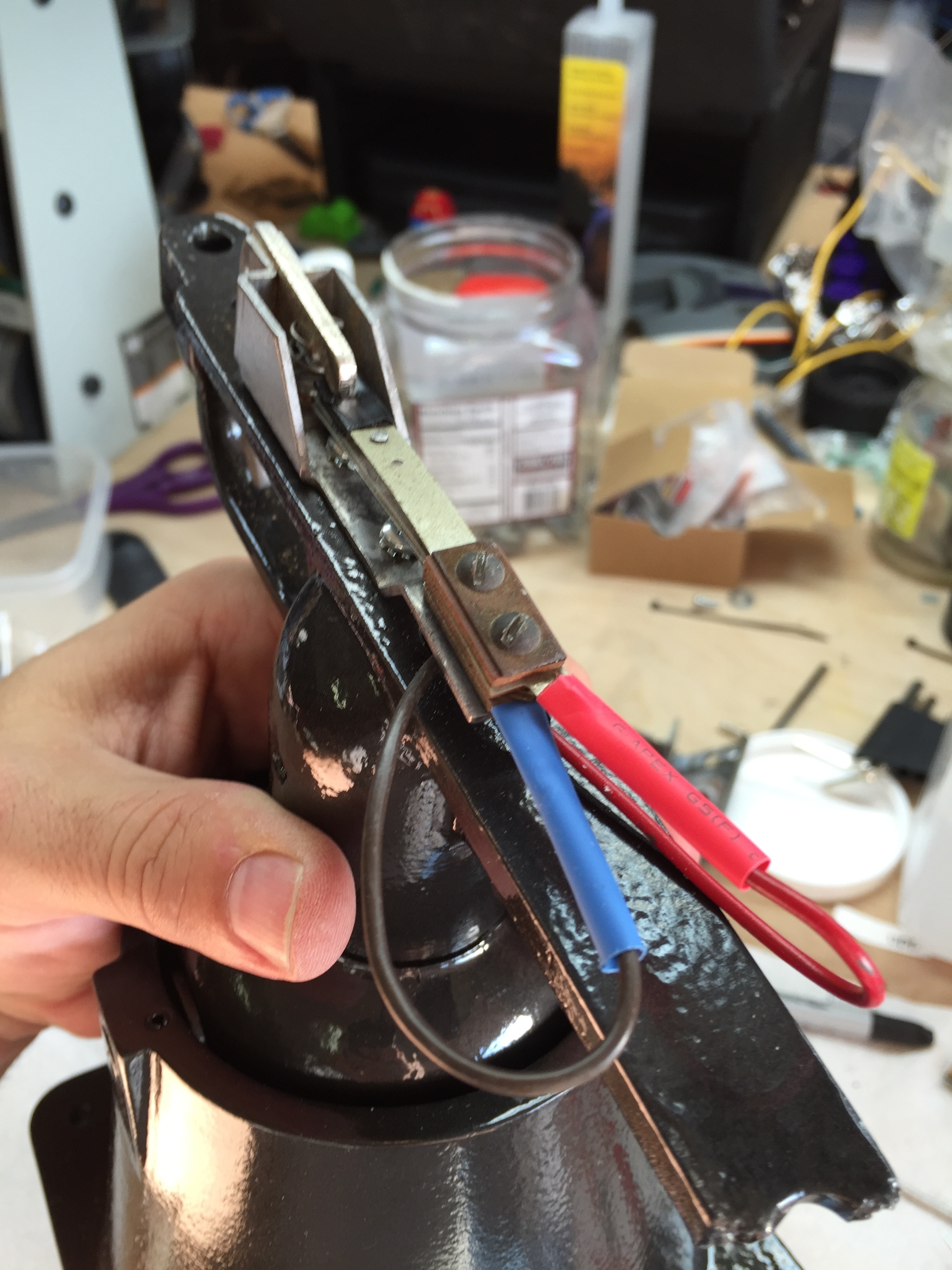
Here’s what the fixed and re-assembled stylus arms look like. The first is the top arm that registers horizontal movement, the second is the bottom arm that registers vertical movement, and the third/fourth is a picture of where they attach to the gun mount, and the re-coil mechanism.
Remounting the Coin Door
I haven’t mounted the really expensive NOS coin door sticker I bought yet. I figure I’ll leave that for last so I won’t accidentally ruin it while I’m working on the game.
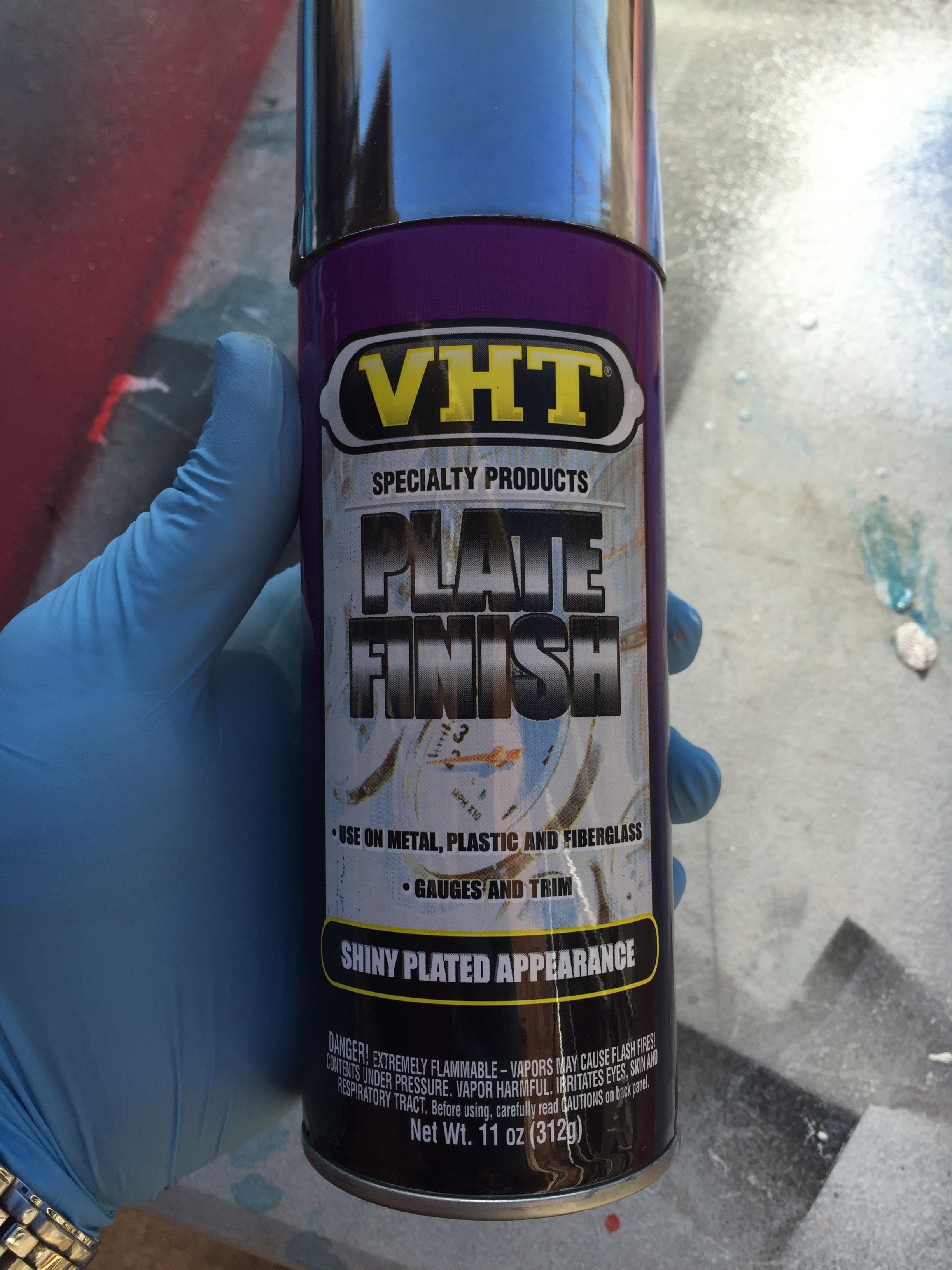
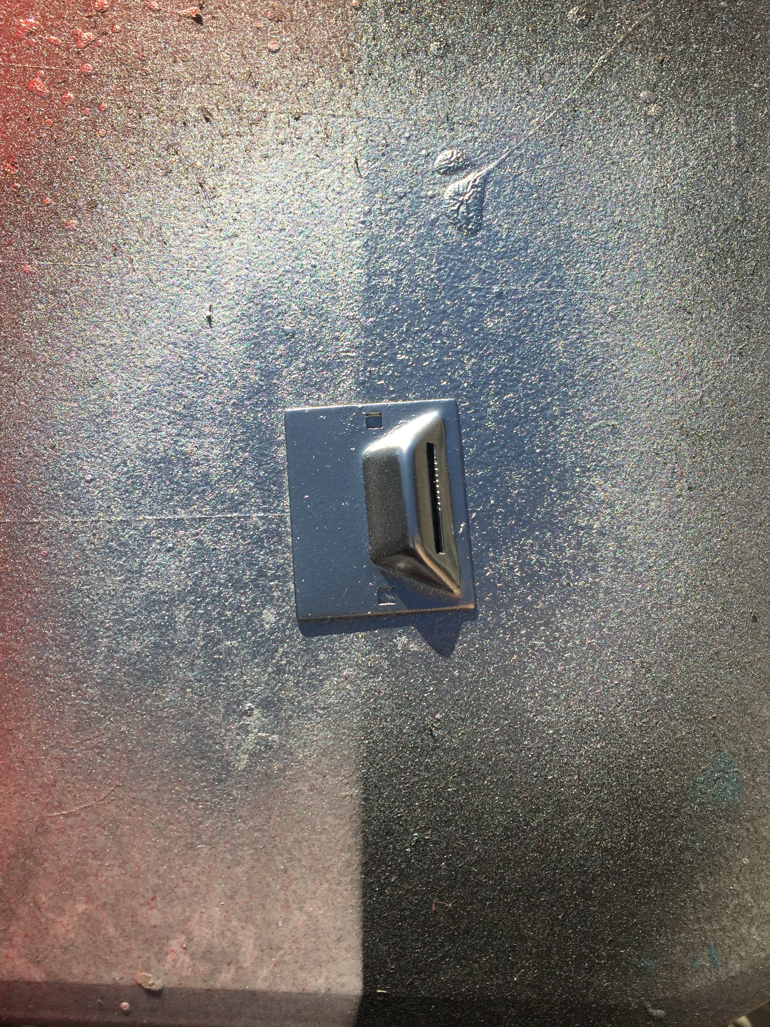
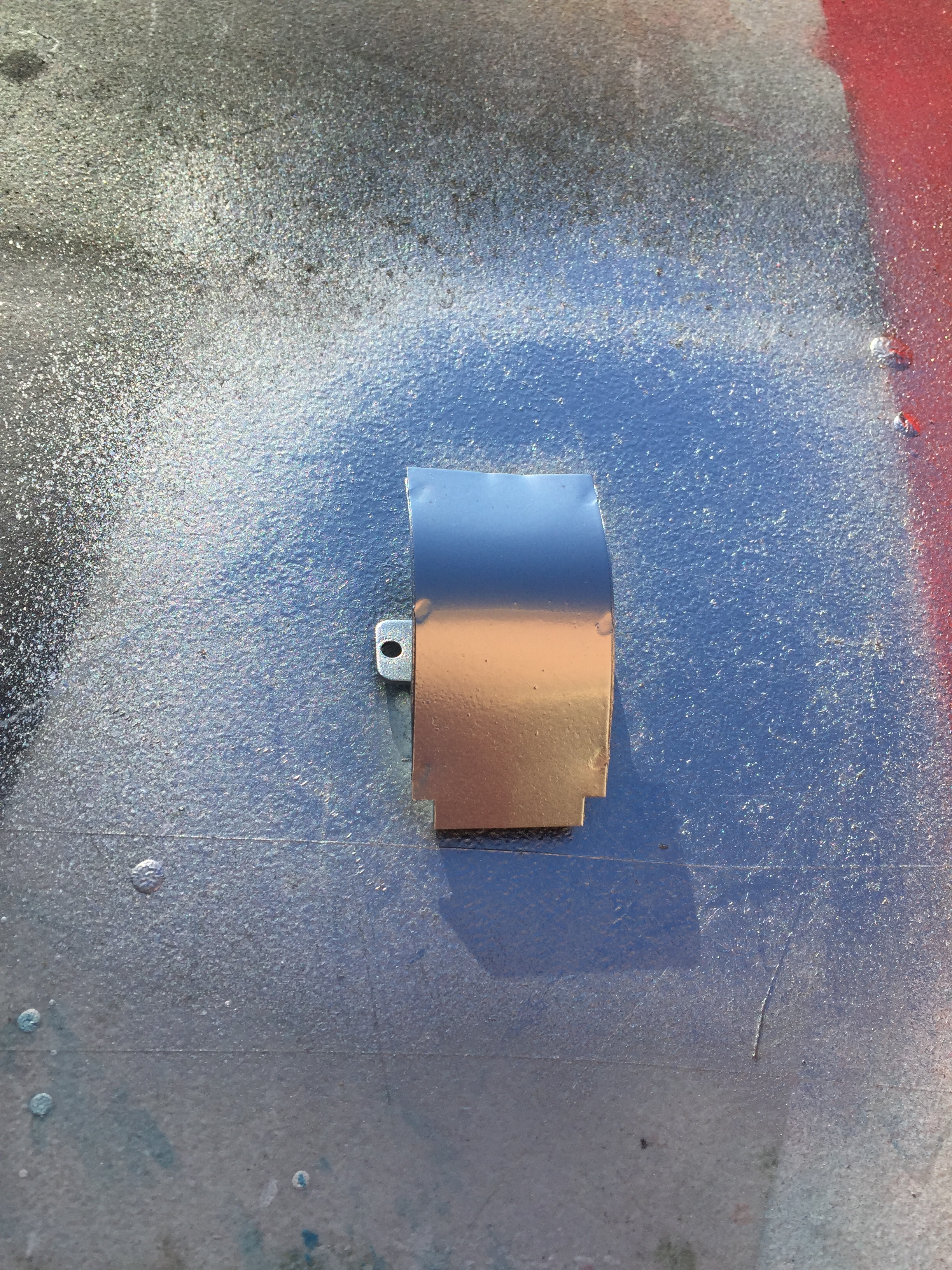
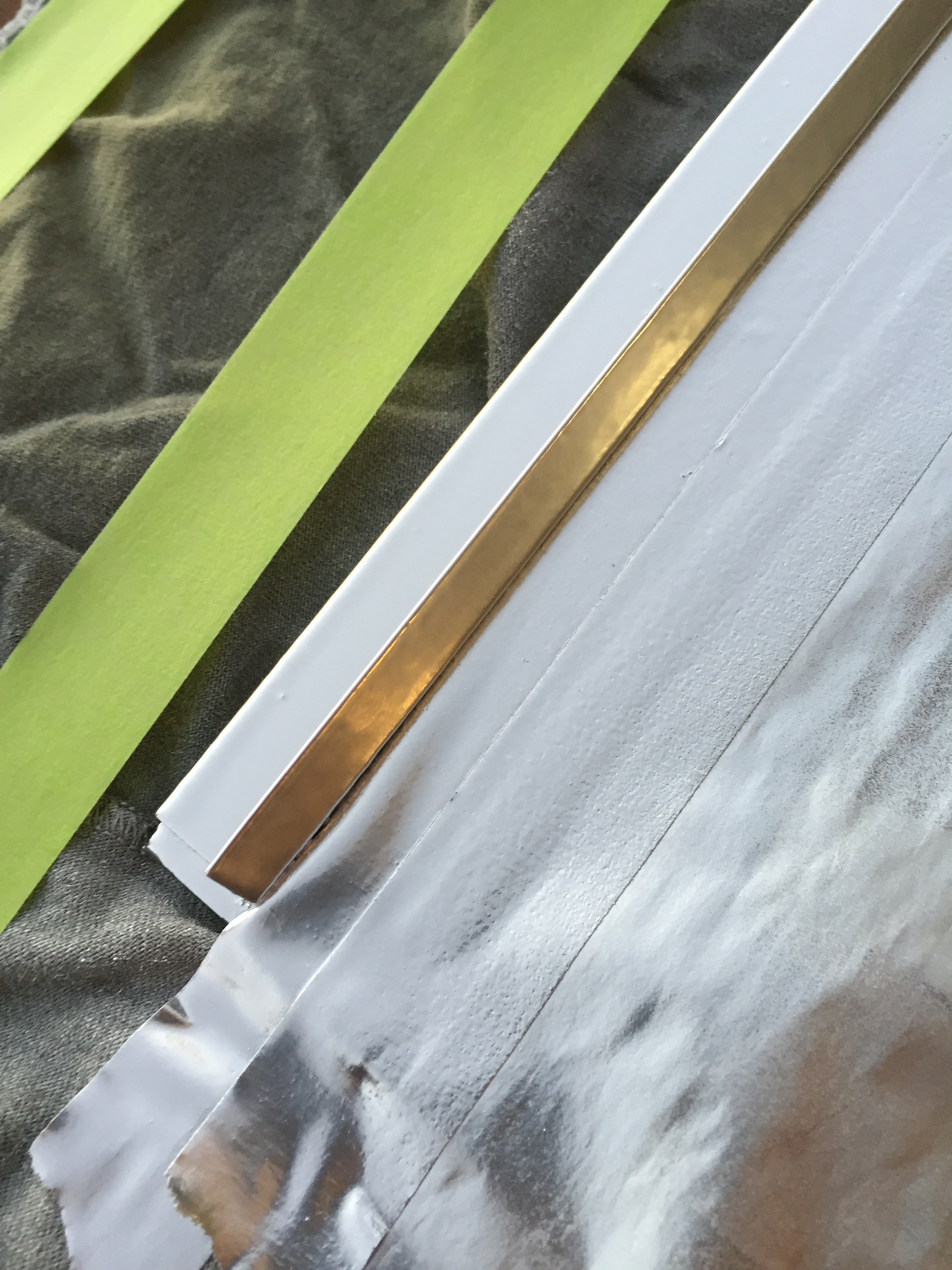
I tried out some chrome plate paint to see how it would look on the some of the metal parts where I just could not polish back a good finish. I think it worked pretty well. The product I bought was “VHT PLATE FINISH” I used it on an old coin entrance plate, and on the metal lift bracket on the bottom of the back glass. Here’s some pictures.
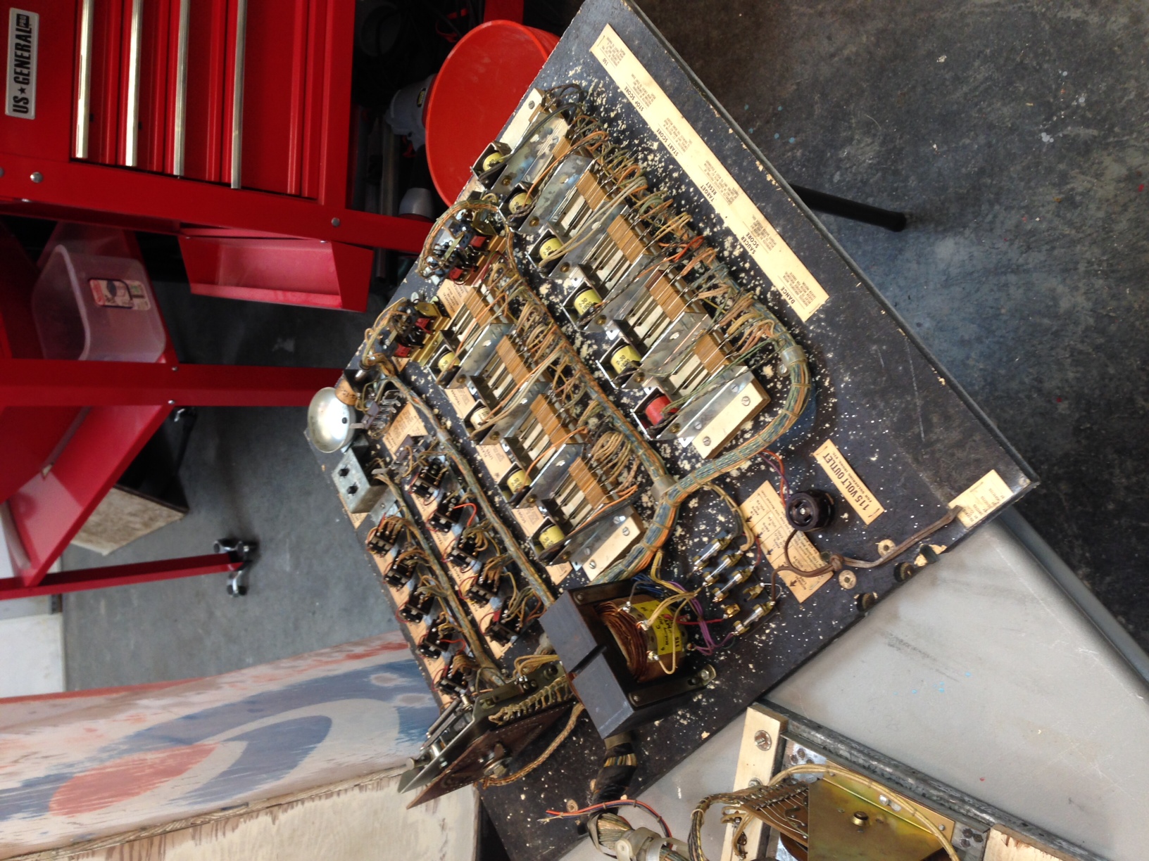
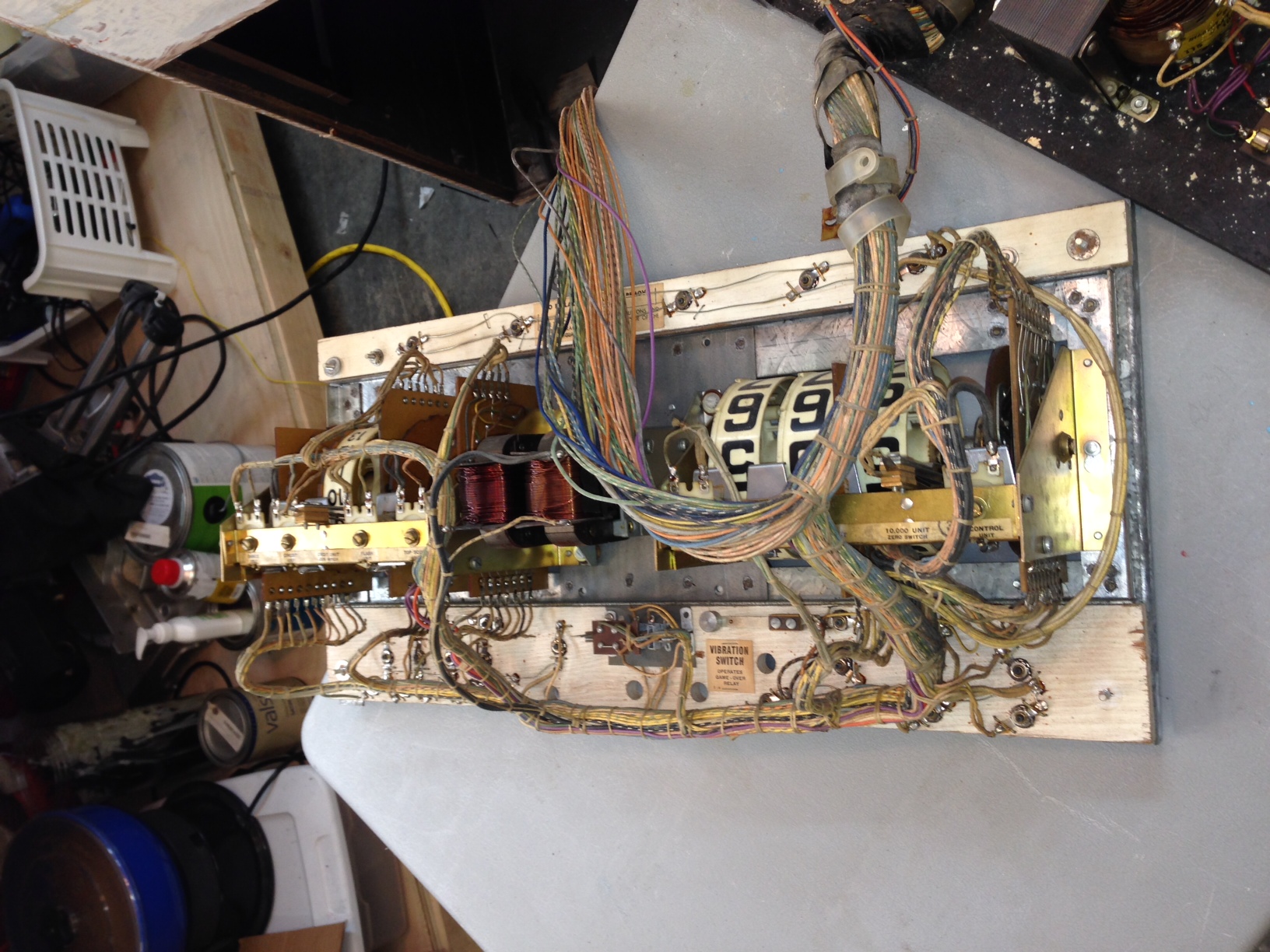
Credit and Score Reels
Once I got the machine all back together, I was dying to plug it in and see how it worked. I realized very quickly I had made a very bad assumption that the score reels and credit reel assembly didn’t need any work. When I turned the game on, it immediately tried to reset, and I could see the motor that drives this mechanism was struggling mightely to try to reset these reels. I’ve read on other websites that people HATE these midway score assemblies, and just looking at it is quite daunting! There are so many parts to the thing, and almost the whole thing has to come out of the game in order to work on it. Here’s some examples of taking it apart (in sequence). Here’s Clay’s guide to these score reels http://www.pinrepair.com/em/index2.htm#midway
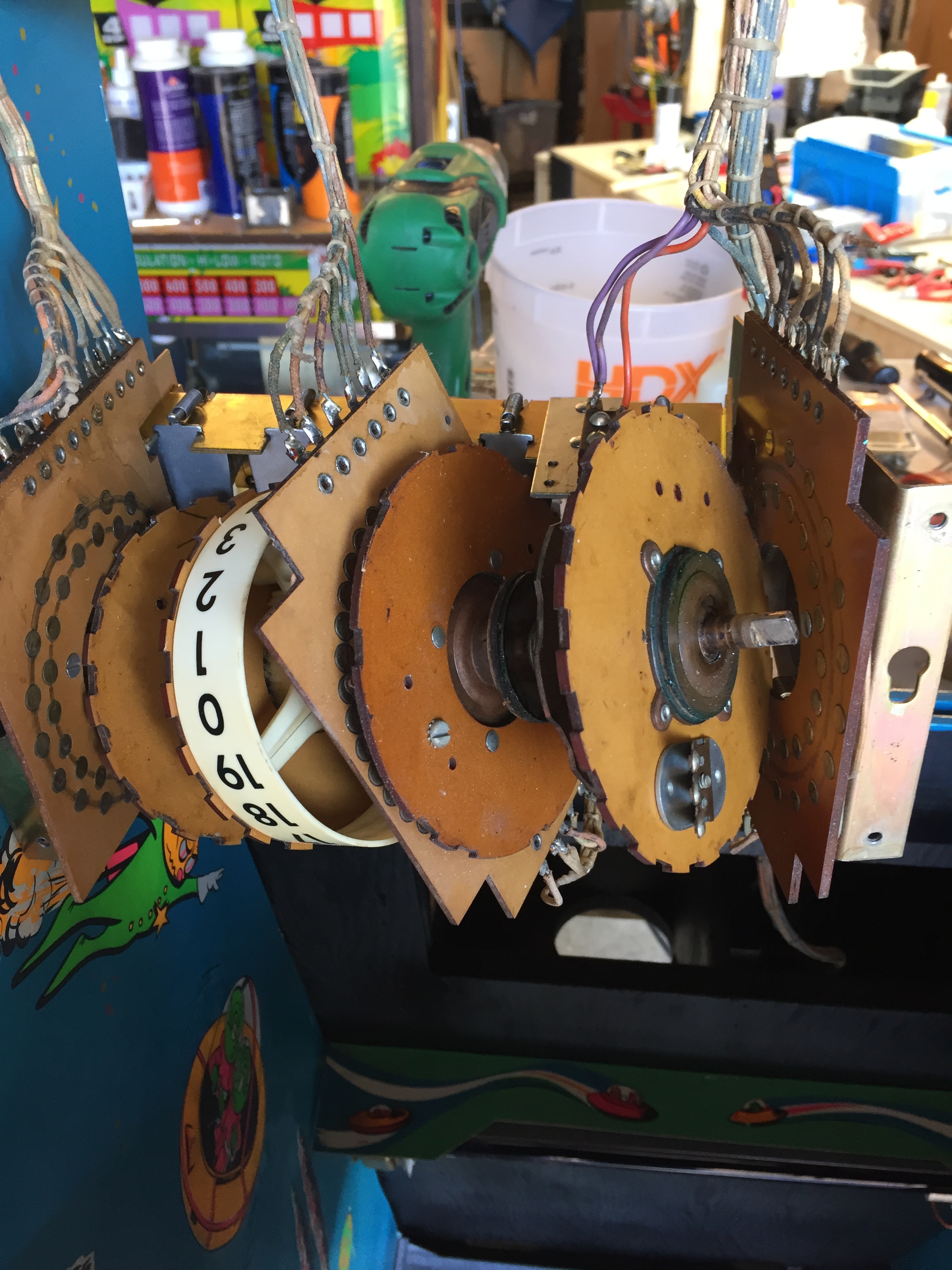
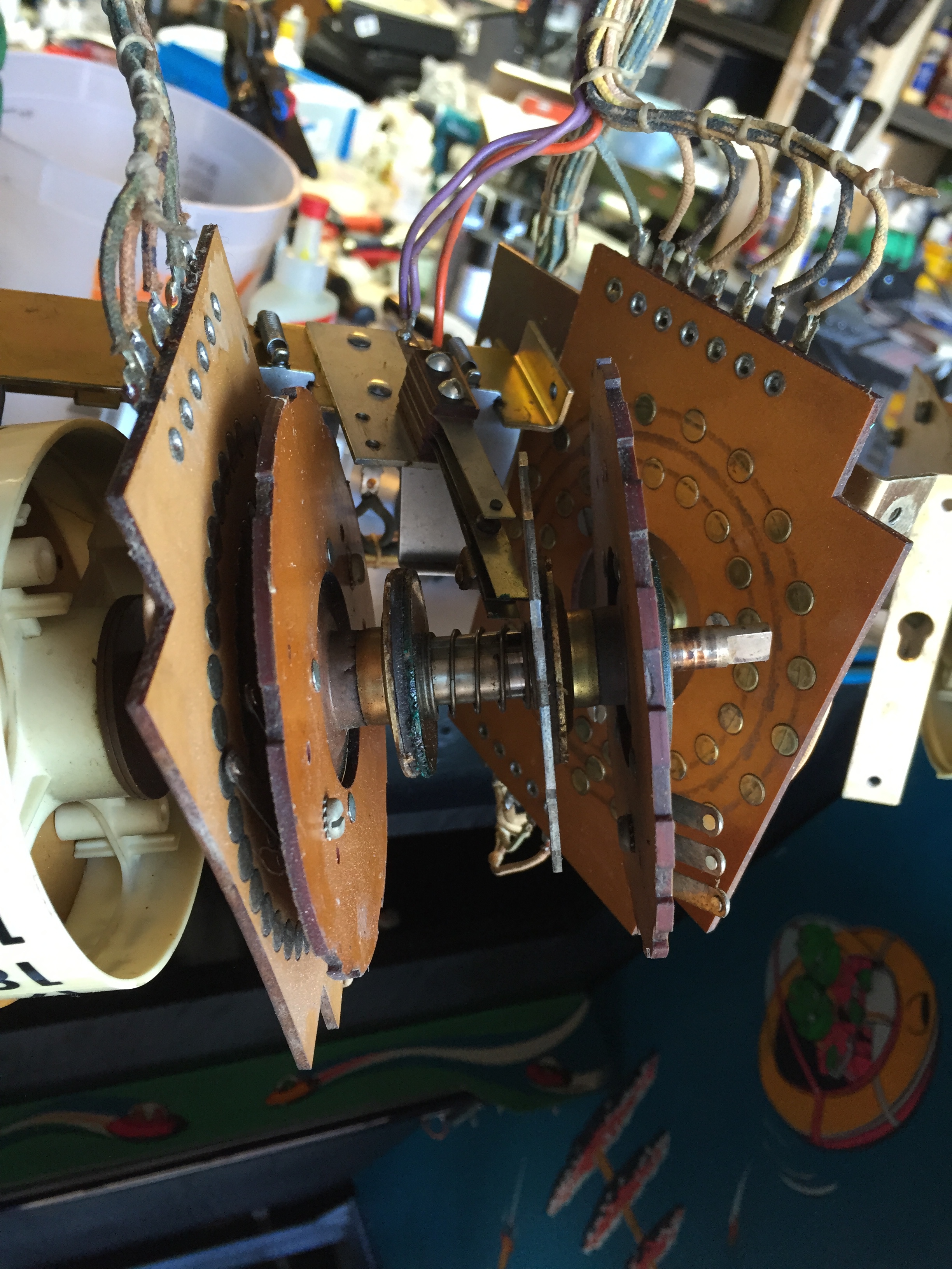
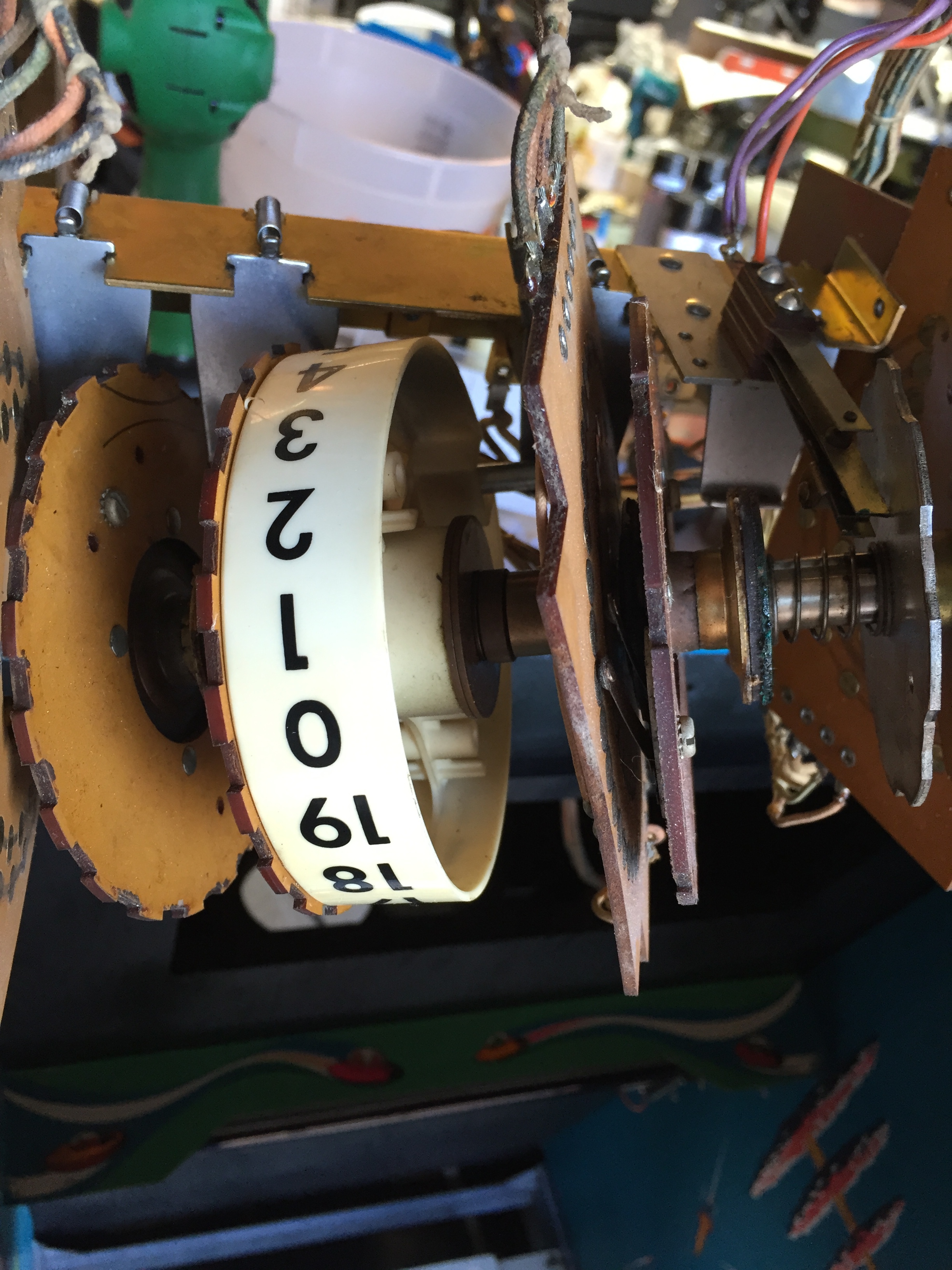
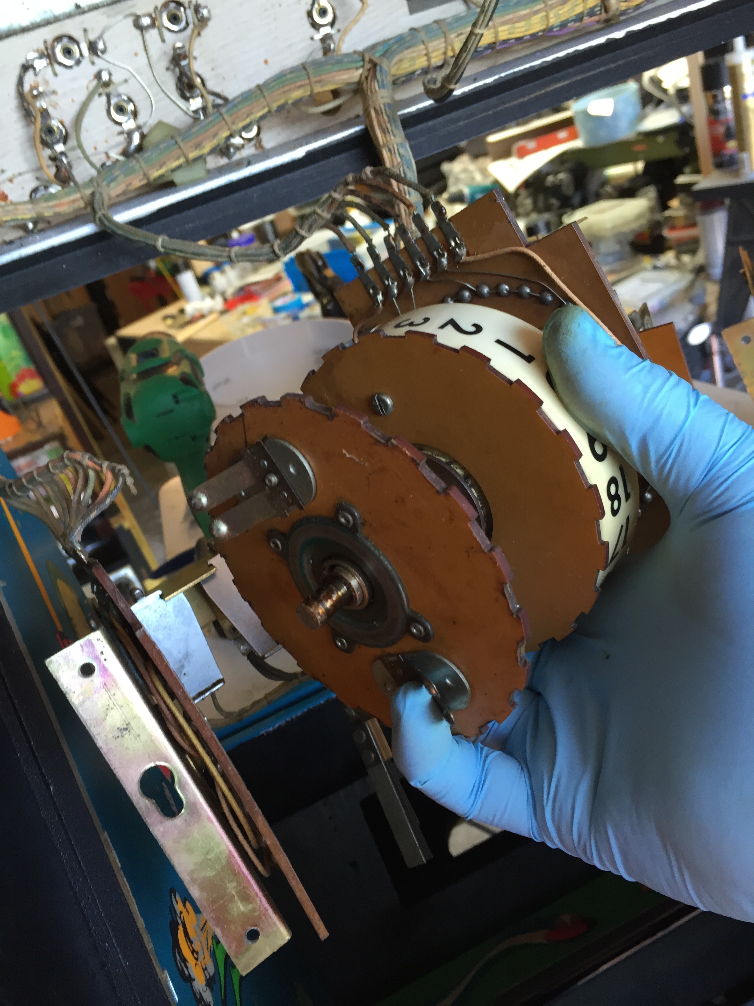
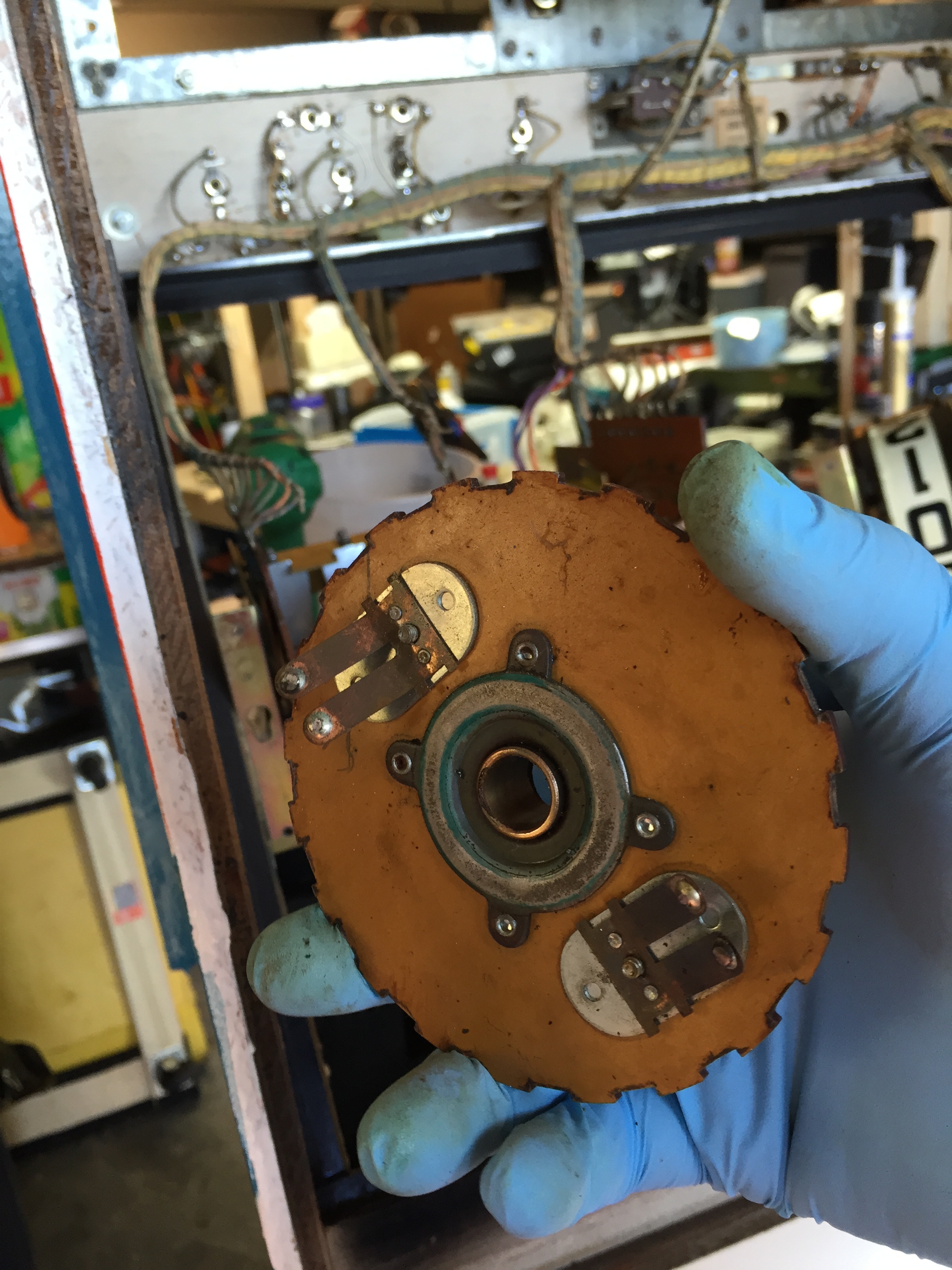
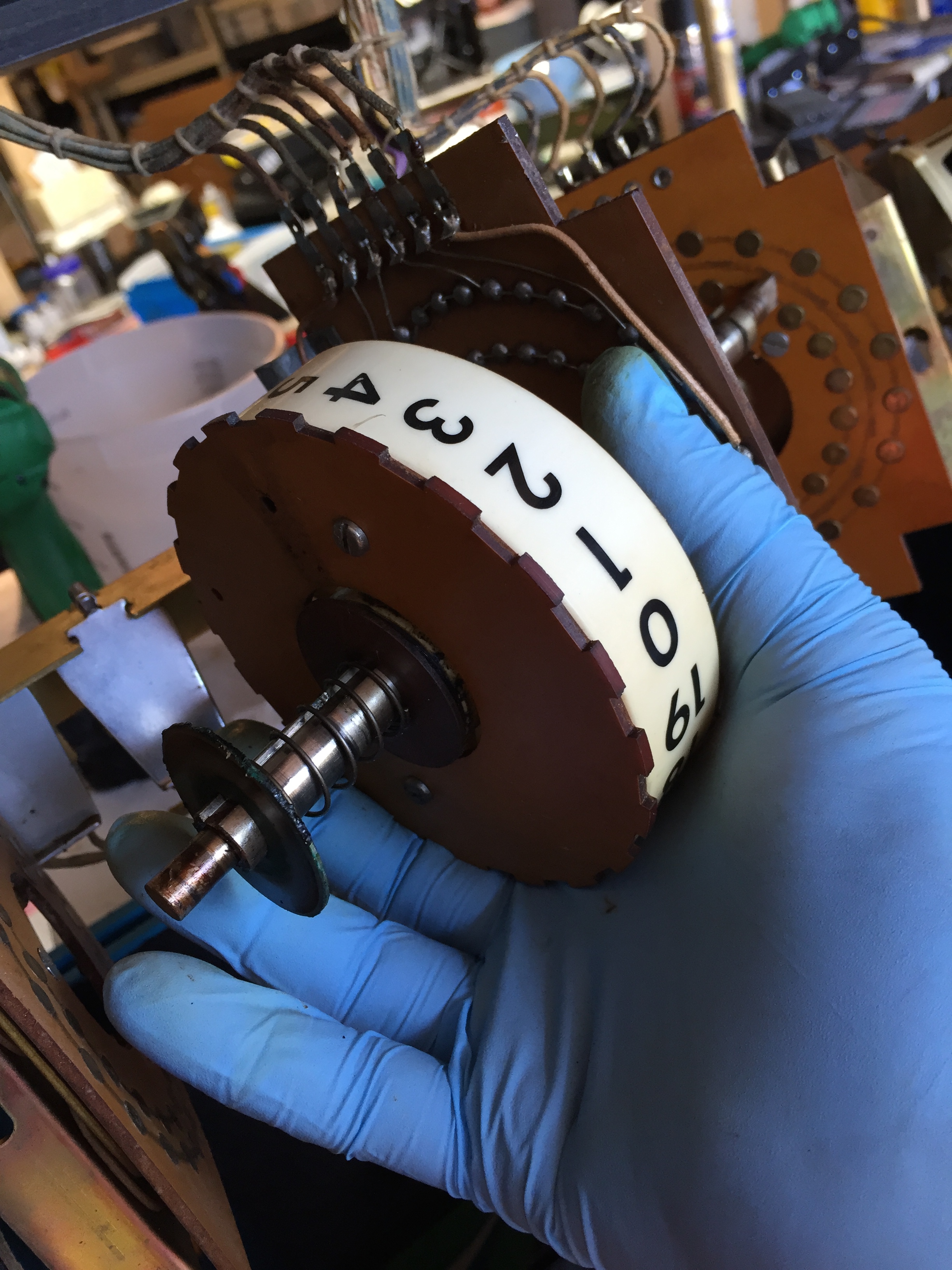
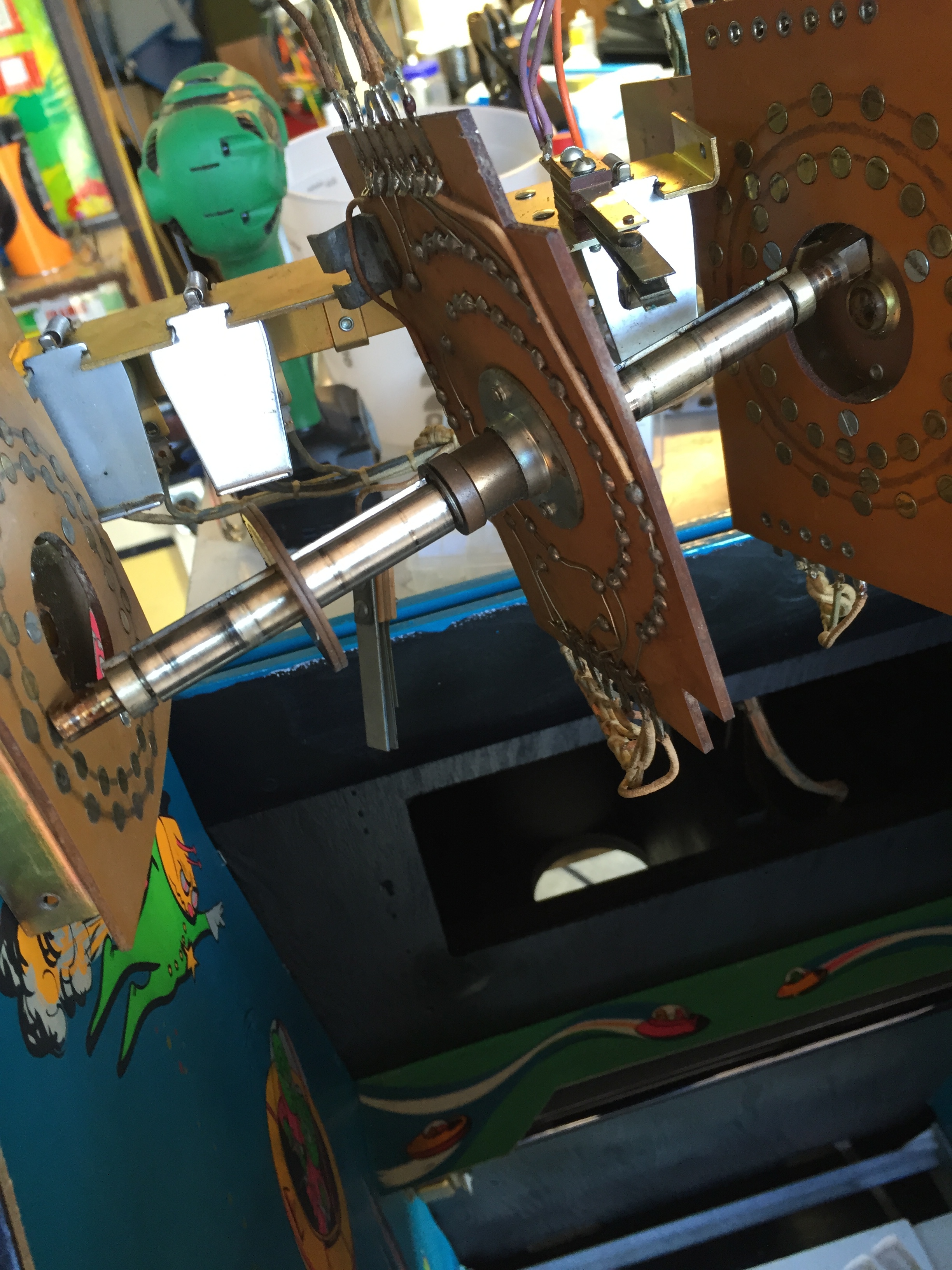
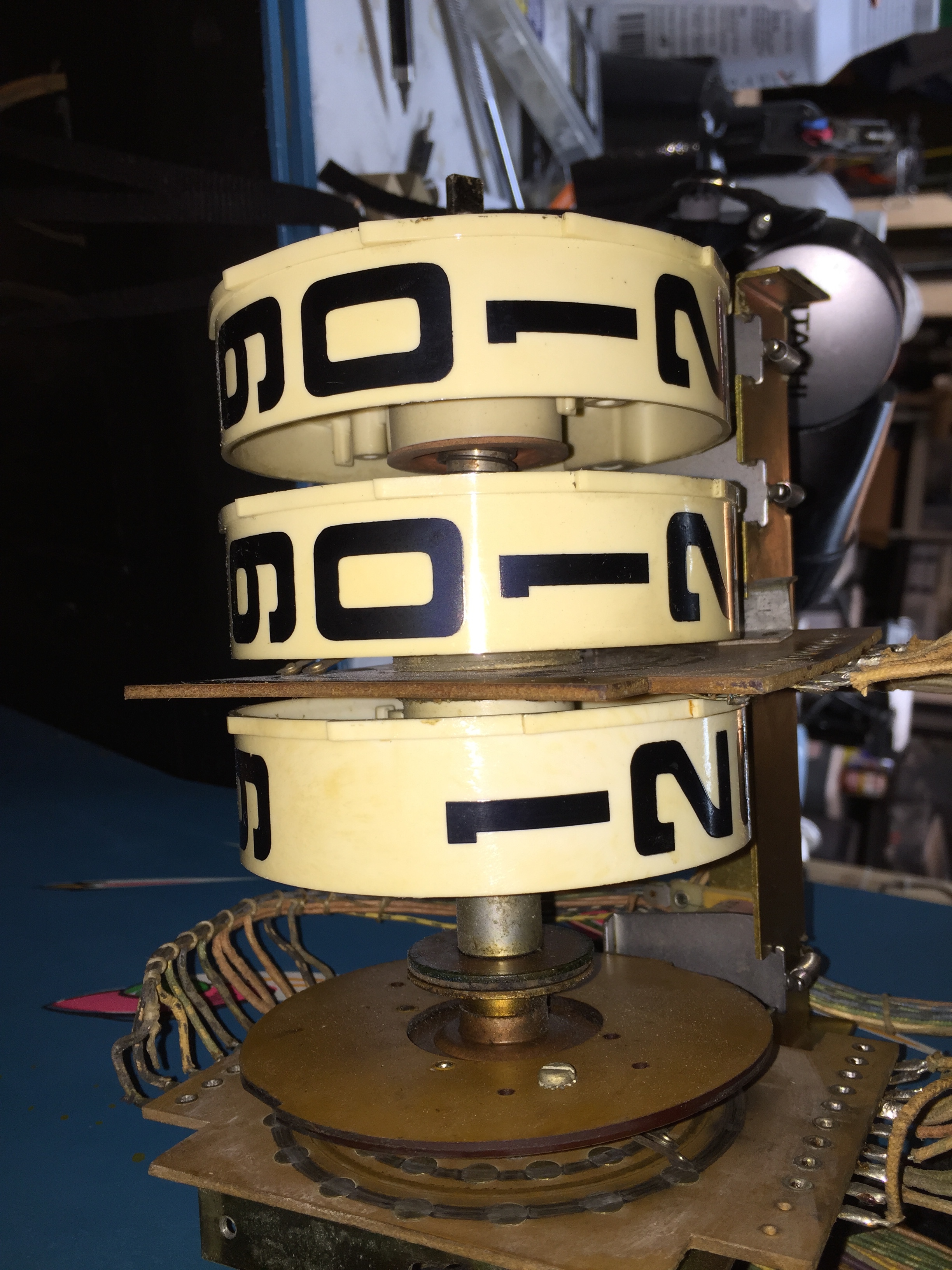
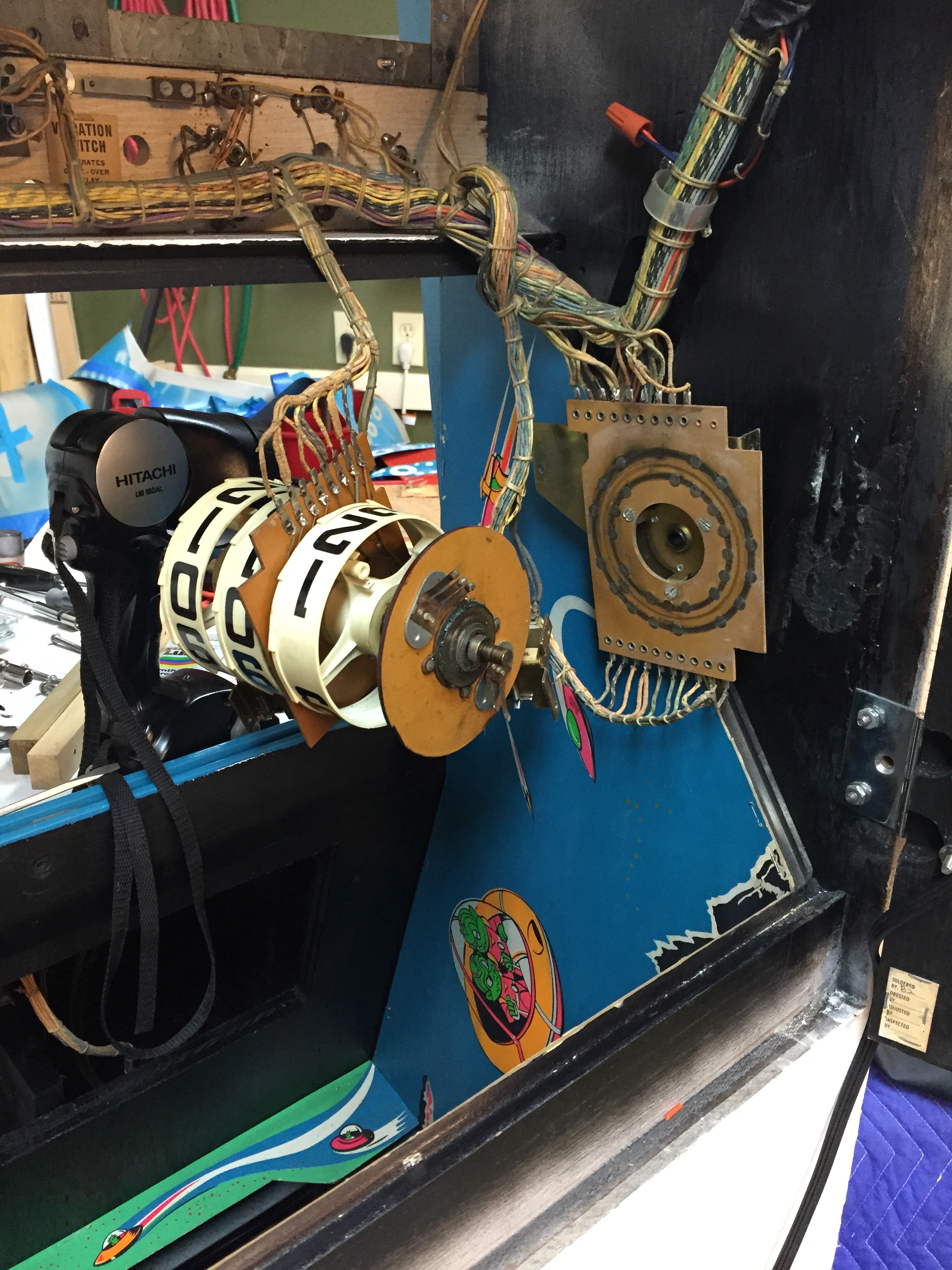
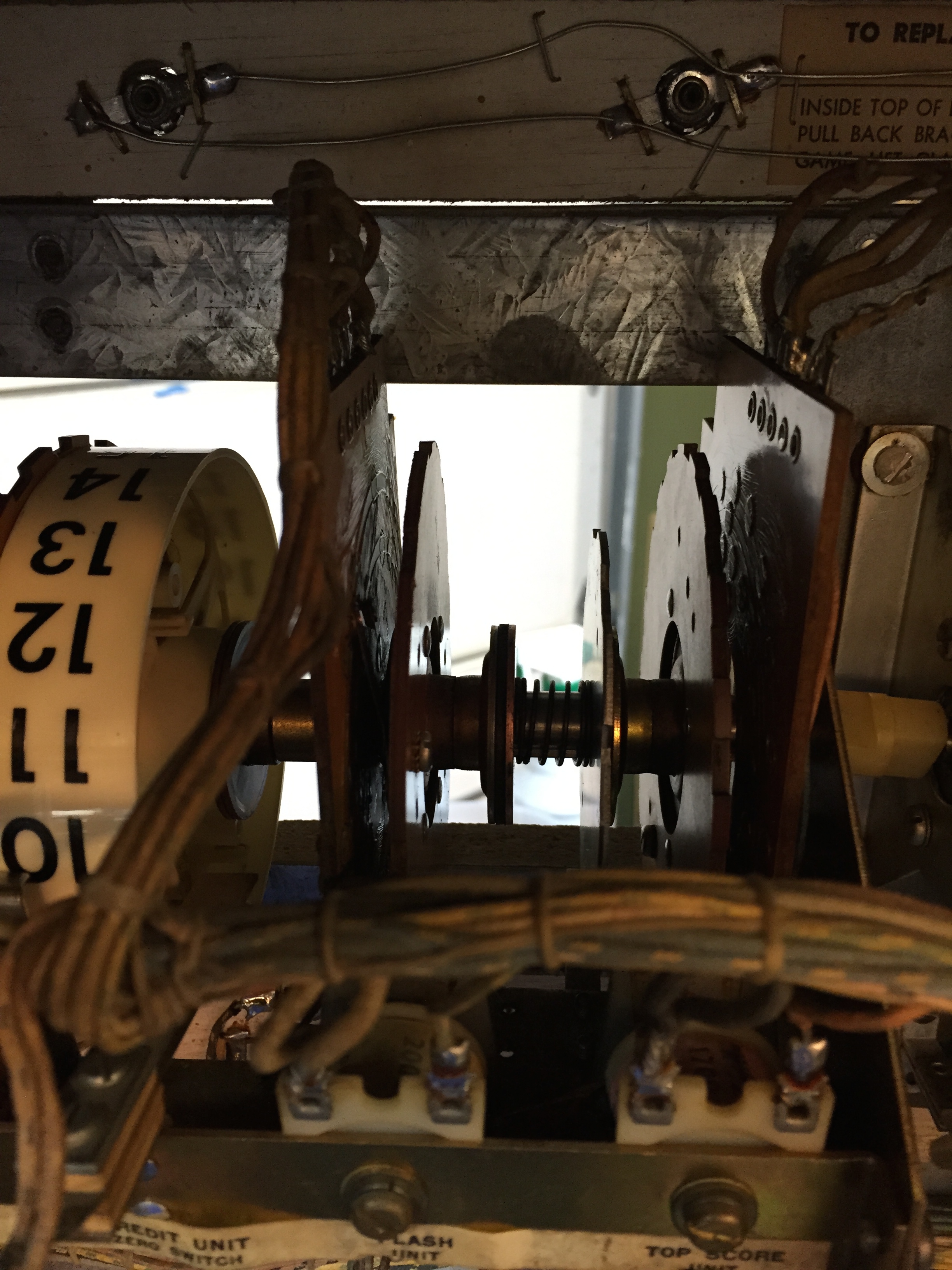
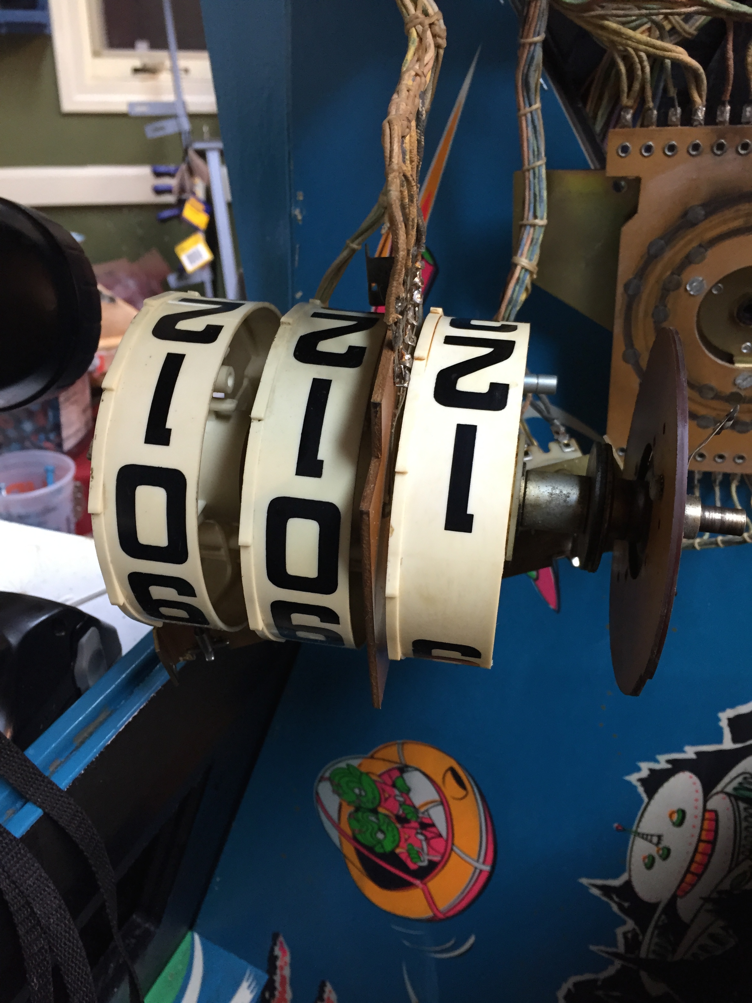
There are a million parts, and they were all gummed up with old solidified grease. The sad thing is I don’t believe hardly any of this assembly should be greased, it’s mostly nylon on metal, or metal on leather (yes, you read correctly) leather. They used leather in the clutches between the different discs. This unit controls credits, dancing for the dancing target, score, and a few other functions. I’m sure it seemed like a good idea at the time, but man, this was a lot of work. It took me about 5-6 hours to completely disassemble the whole thing, piece by piece, clean each piece with alcohaul and mean grean, and then reassemble it. It works great now, but only got me to the point now where I now have more diagnosis of the startup process of the game, as now that it moves freely, it still isn’t initializing correctly. I think I’ve got some contacts that aren’t making good contact, and it’s not registering the home position of either some of the discs of this assembly, or the target assembly…
Just goes to show you, I should have listened to the little voice in my head and disassembled this thing and cleaned it while it was out of the machine, not waited until I had it all back together!!!
Reassembling the Game
I still have a little cosmetic work to do, but I decided to go ahead and get the rest of the game assembled to make sure things are working correctly.
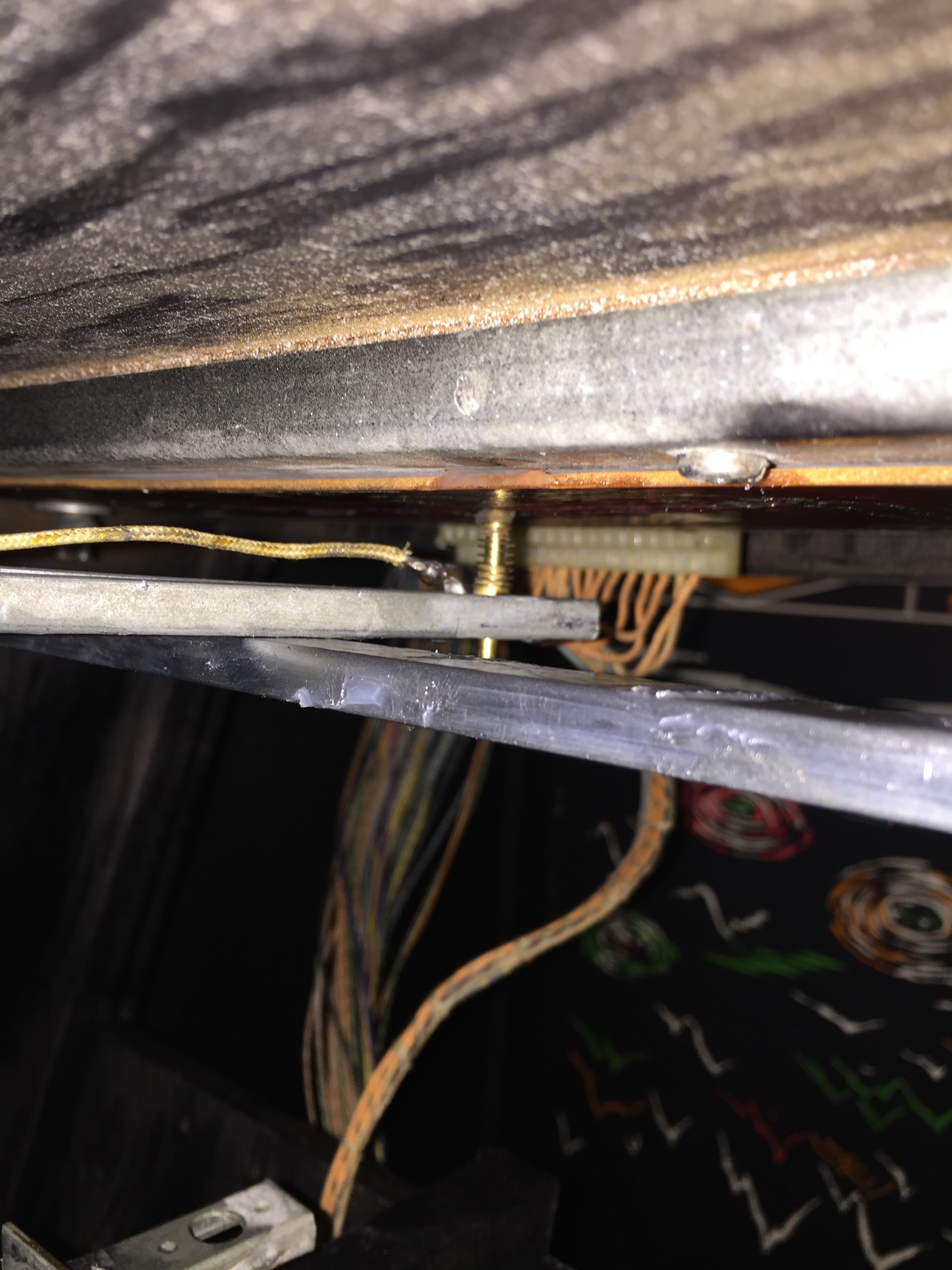
I got everything back together enough to test out the game, and most things were working correctly, but the dancing target would just run to one side or the other, and would not trip the relay to change direction. This problem really baffled me for about 4 days. I kept looking at the schematic, then testing voltages, and continuity and just couldn’t figure out why the horizontal relay wouldn’t trigger and change the direction. I finally pulled the target assembly out and started to carefully go through the wiring to the horizontal and vertical motors.
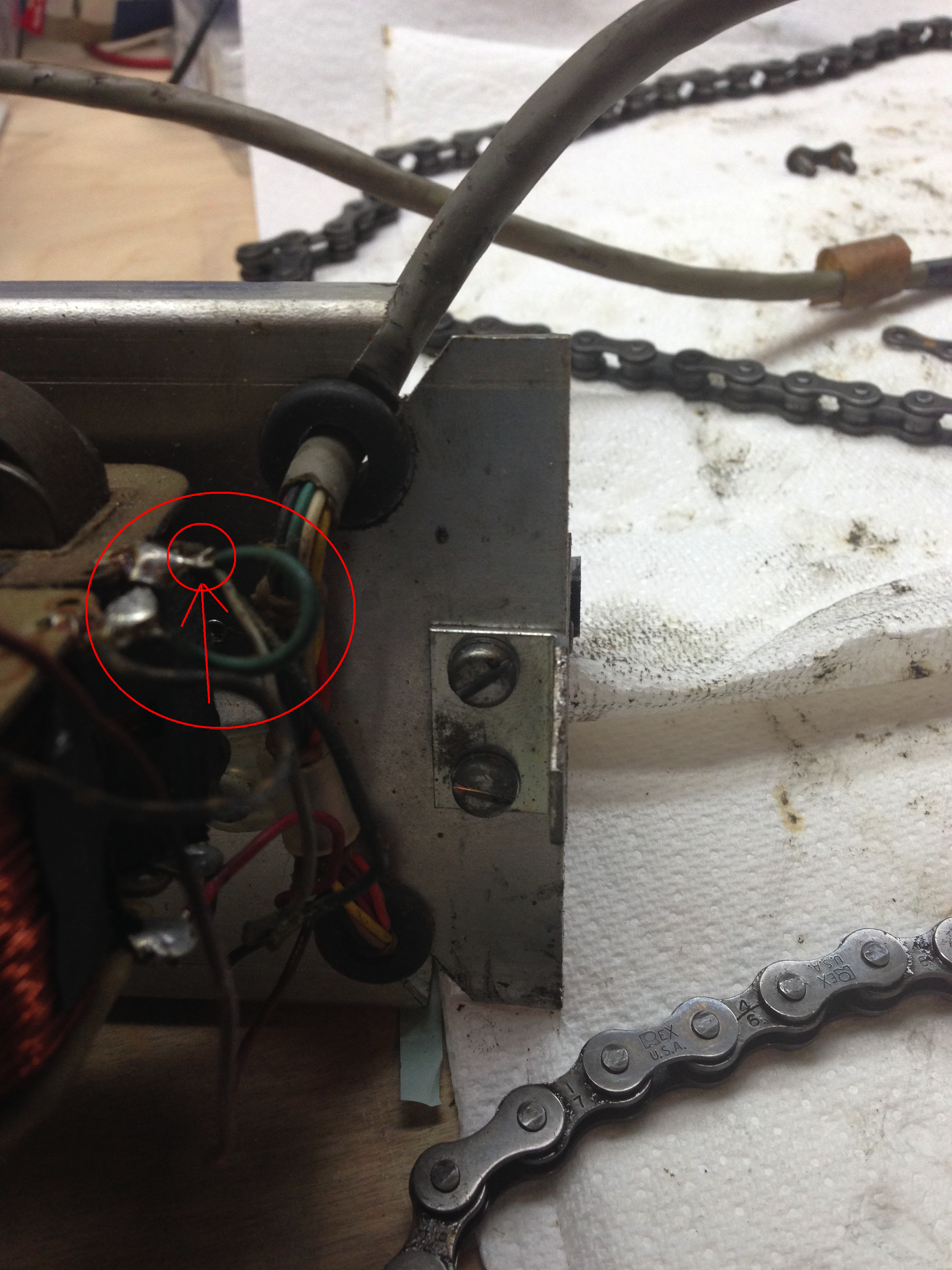
The problem ended up being the gray wire (in the little circle). When I was checking continuity on it, it appeared good, but I was actually checking the path for the other wire soldered on this terminal back through the connector. As I desoldered it, I realized the wire was broken within its insulation, and it was being held on to the terminal by some melted insulation and some flux from the soldering, so it seemed like it was soldered on, but was actually not making contact. As soon as I fixed that, it worked great.
So I put the target assembly back in the game, cleaned the glasses and put them in the game. I put the gun stock/barrel back on the gun mount. I cut a back door for the game, and installed that. I put a new black light in the game, and then started testing.
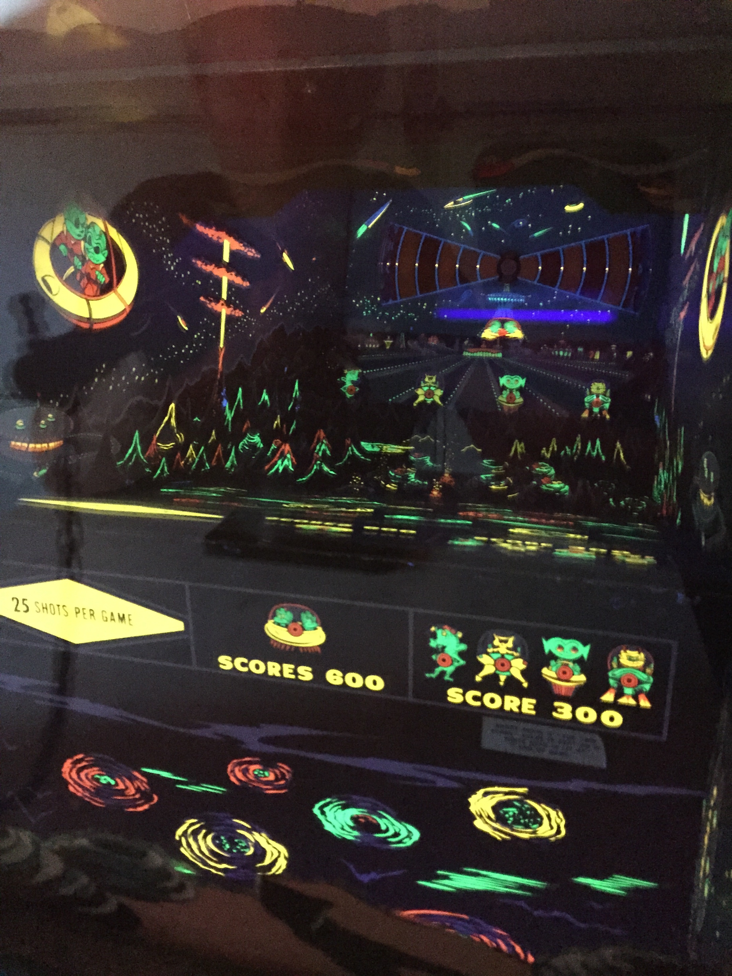
You can see that the dancing target has moved position in the two pictures above.
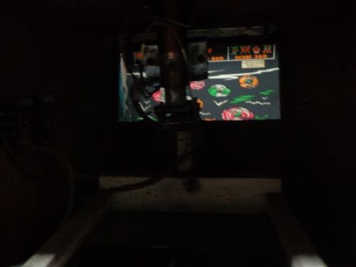
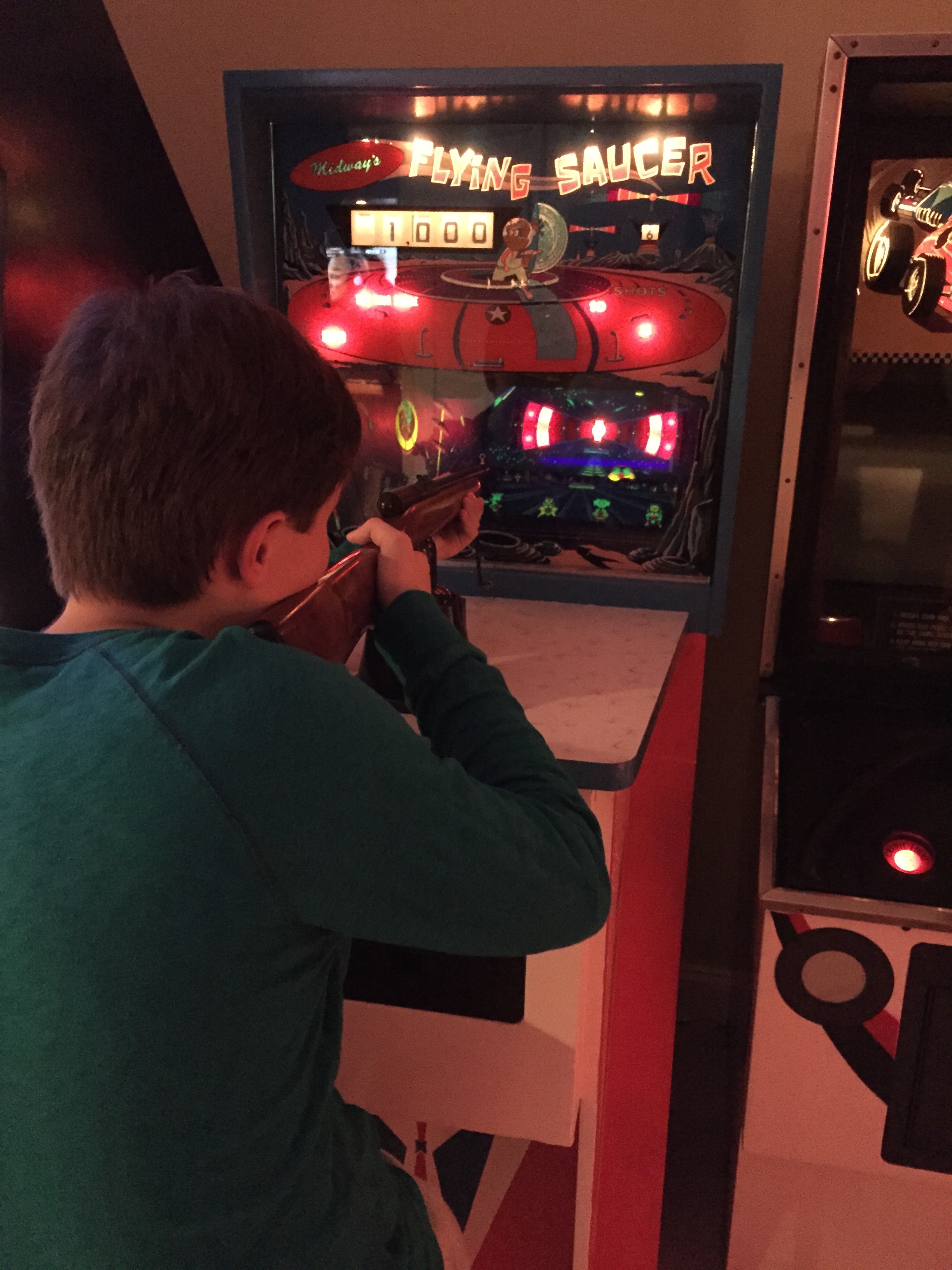
Here’s a video of the game in play. It’s tough to see it very well because of the black light, but you you can see some of the targets being hit, and how the flying saucer moves. http://youtu.be/VMtAKUUqWyM
New Power Switch
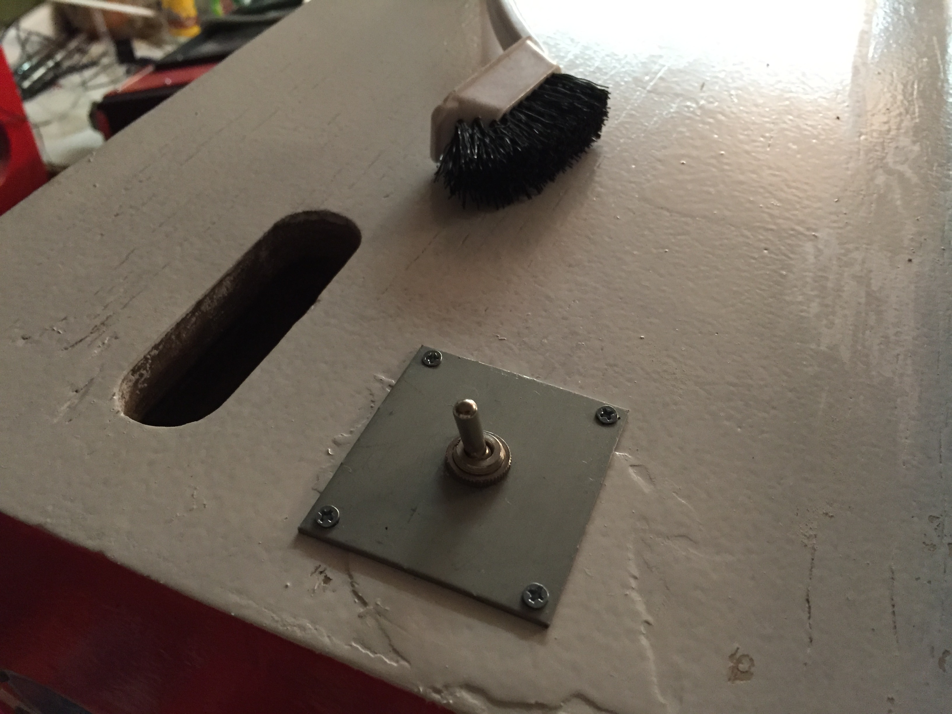
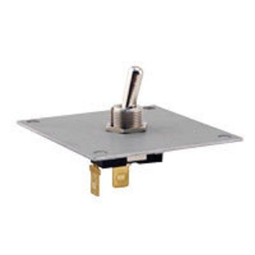
The old power switch was really shot, so I threw it away when I redid the cabinet. I put a new power switch on. I used a Happ replacement switch which I got from eBay from seller http://stores.ebay.com/dirtcheaptrading/. I originally found these when I was replacing the power switch on my Royal Hawaiian shuffle bowler – that switch was completely missing, and these were as close to the original part as I could find. I like these switches because they come with a metal plate, so if the opening for the switch is in rough shape, they can completely cover it, plus they give a very sturdy mounting point for the switch.
I mounted it through a hole in the top of the cabinet, and had to splice in some new wires to make the length reach. I also updated the power cord, and ran it through the back door with some space connectors so it could be replaced next time without unsoldering wires.
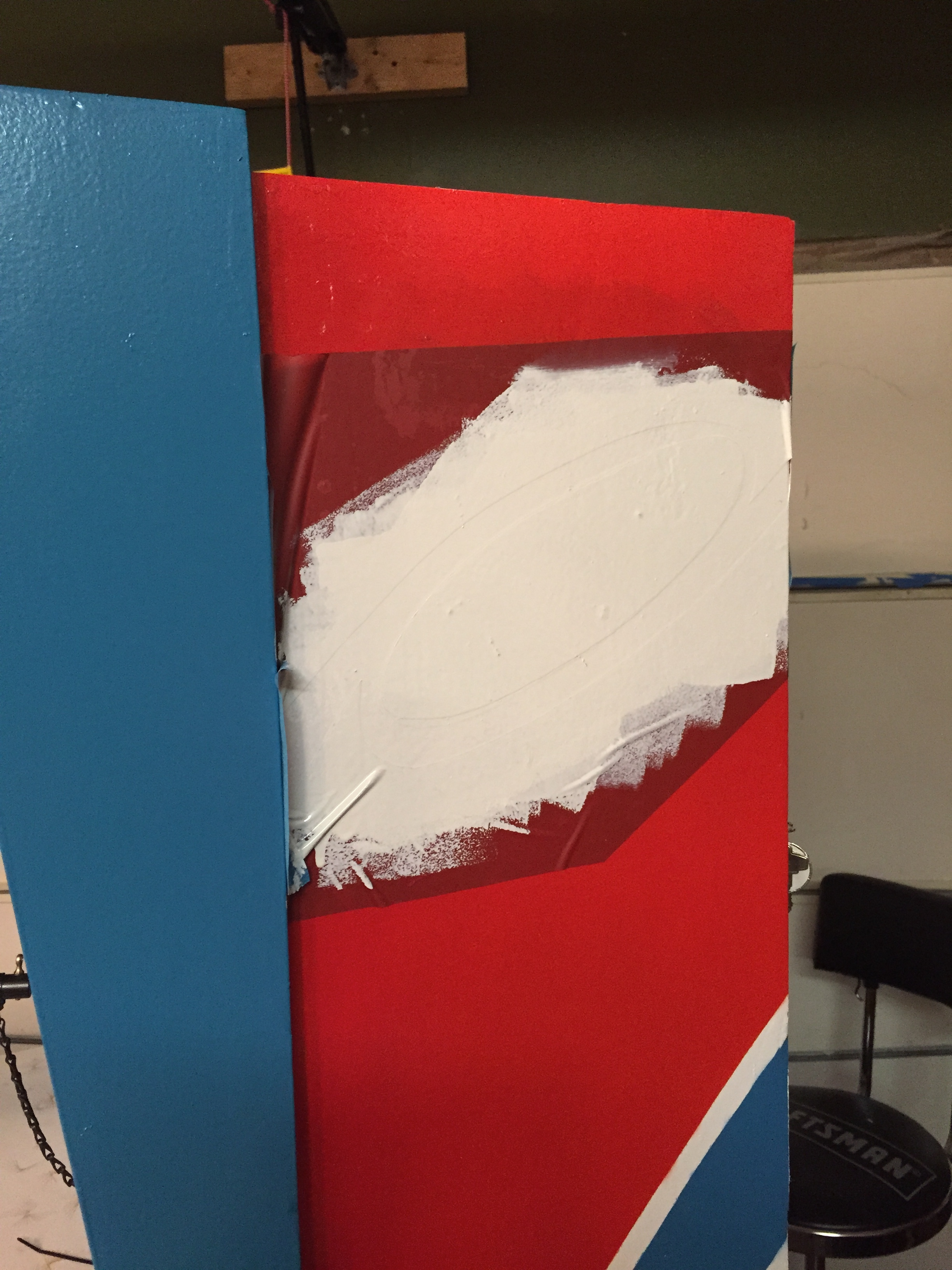
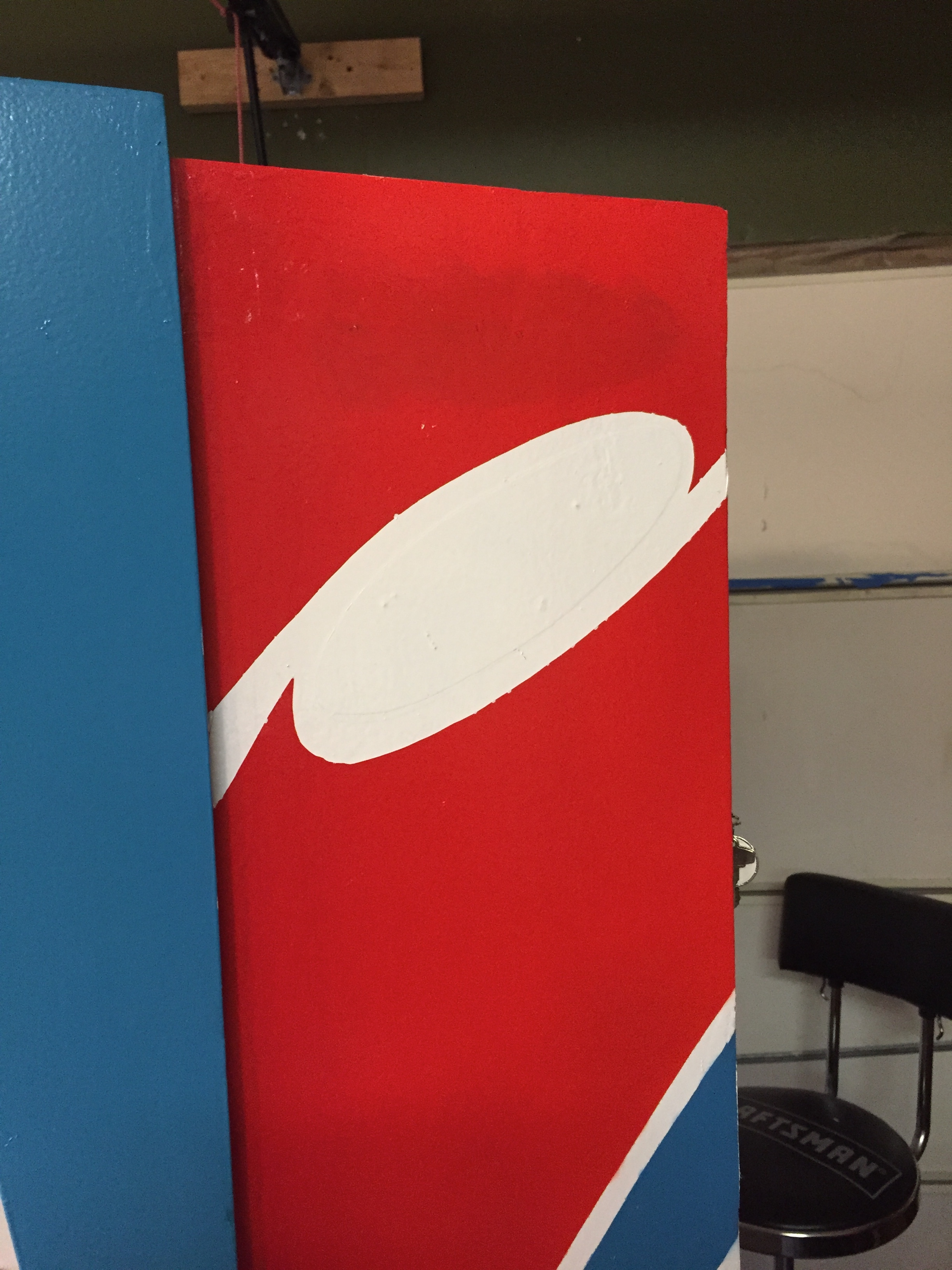
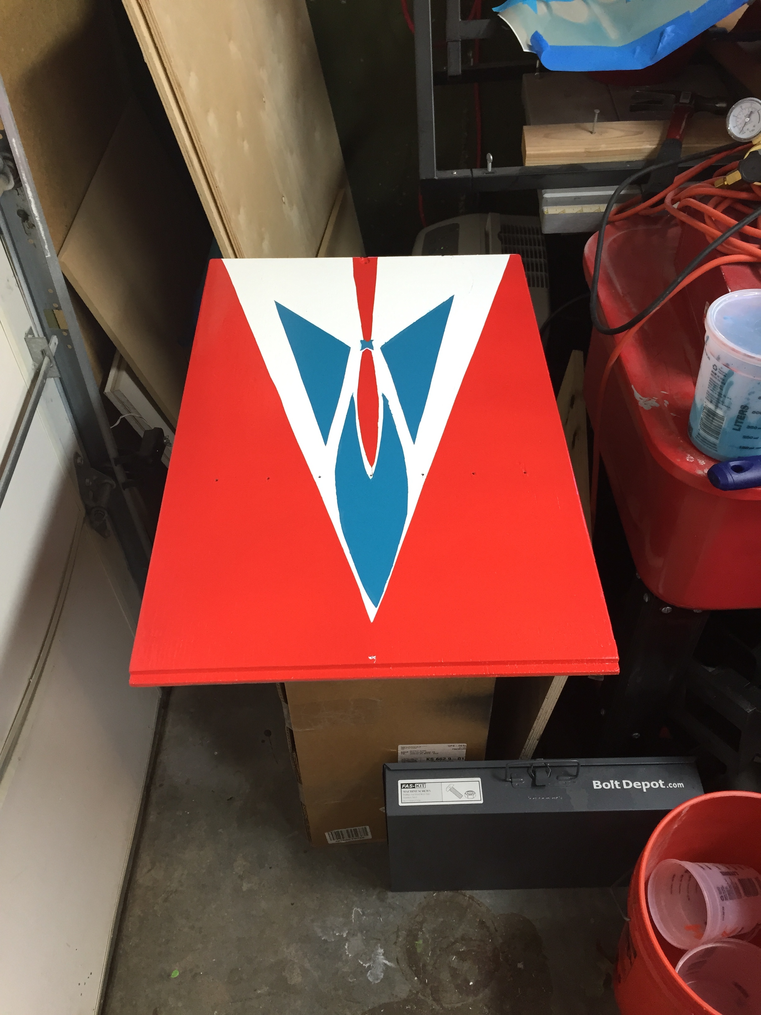
Fixing my Stencilling Screw-up
When I painted the red on one side, I forgot to place my top stecil (this would have masked the white of the the “swoosh”).
Here’s the before picture:
Here’s a series of pictures showing the stencil being painted and then after it was done.
Tracing the Front Door Pattern
Here’s my trace of the front door pattern. I laid the tracing paper over the door, and traced the patterns (both the red and blue).
Then I used the same technique I’ve used before where I lay the tracing paper over the stencil material and poke holes through to mark the cut lines. Here’s the red stencil cut from the pattern, laid over the front door.
Here’s the blue stencil cut and ready to go:
First coat of paint sprayed:
After the final coat and with the stencil removed:
Now I have to wait for it to dry, and I can do the blue stencil.
Not perfect, but good enough I think.
Making a Step for Kids
My step is missing (kids need this to be tall enough to sight the gun). I need to make one. I had a hard time finding any examples of what the original step might have looked like. I did find one picture on arcade-museum.com. I found another picture with a slightly different step. These are the only two pictures I can find of any kind of Midway gun game with a step attached.
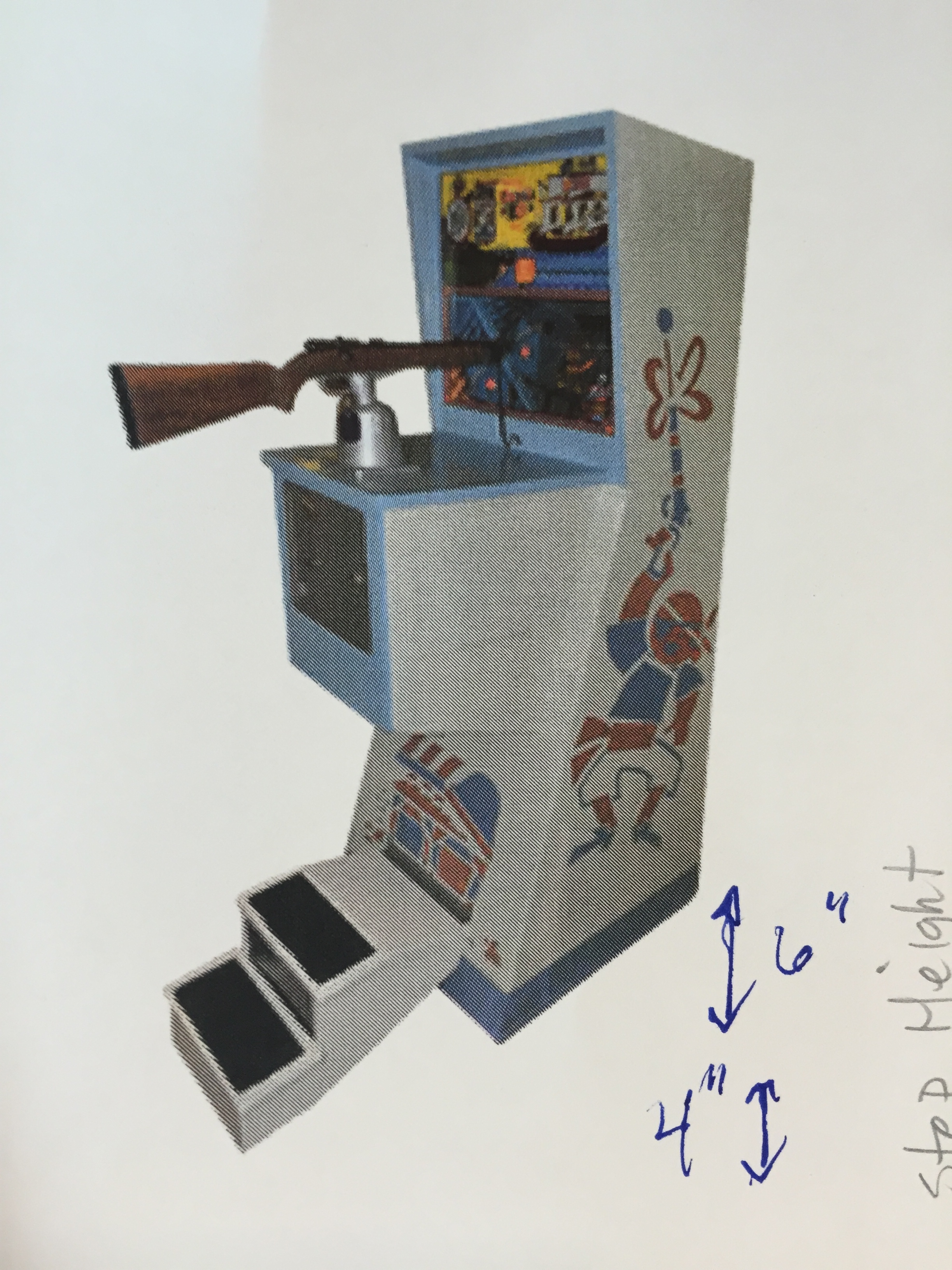
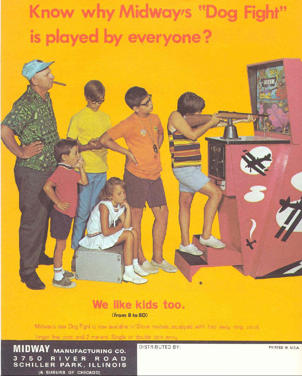
I think the second picture may be closer to my game model. I believe the DogFight is a ’68, whereas my game is a ’67.
Update – I found a better picture of what the step might look like for this game – see below:
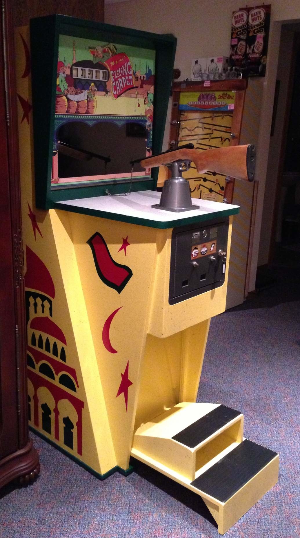
I have to decide which type I’m going to replicate, and then try to derive the dimensions of this and build a replica of this step. It needs to fold up to the game when not being used, and sit firmly on the floor when down. There are a couple of tricky angles. I’m guessing the first step is about 4″, and the second step is about 6″ for a total of about 10″. I believe the step is about 15″ deep (that’s the max it can be without hitting the bottom of the gun assembly). I looks to be about 2/3 as wide as the game itself. This should be enough to get me started.
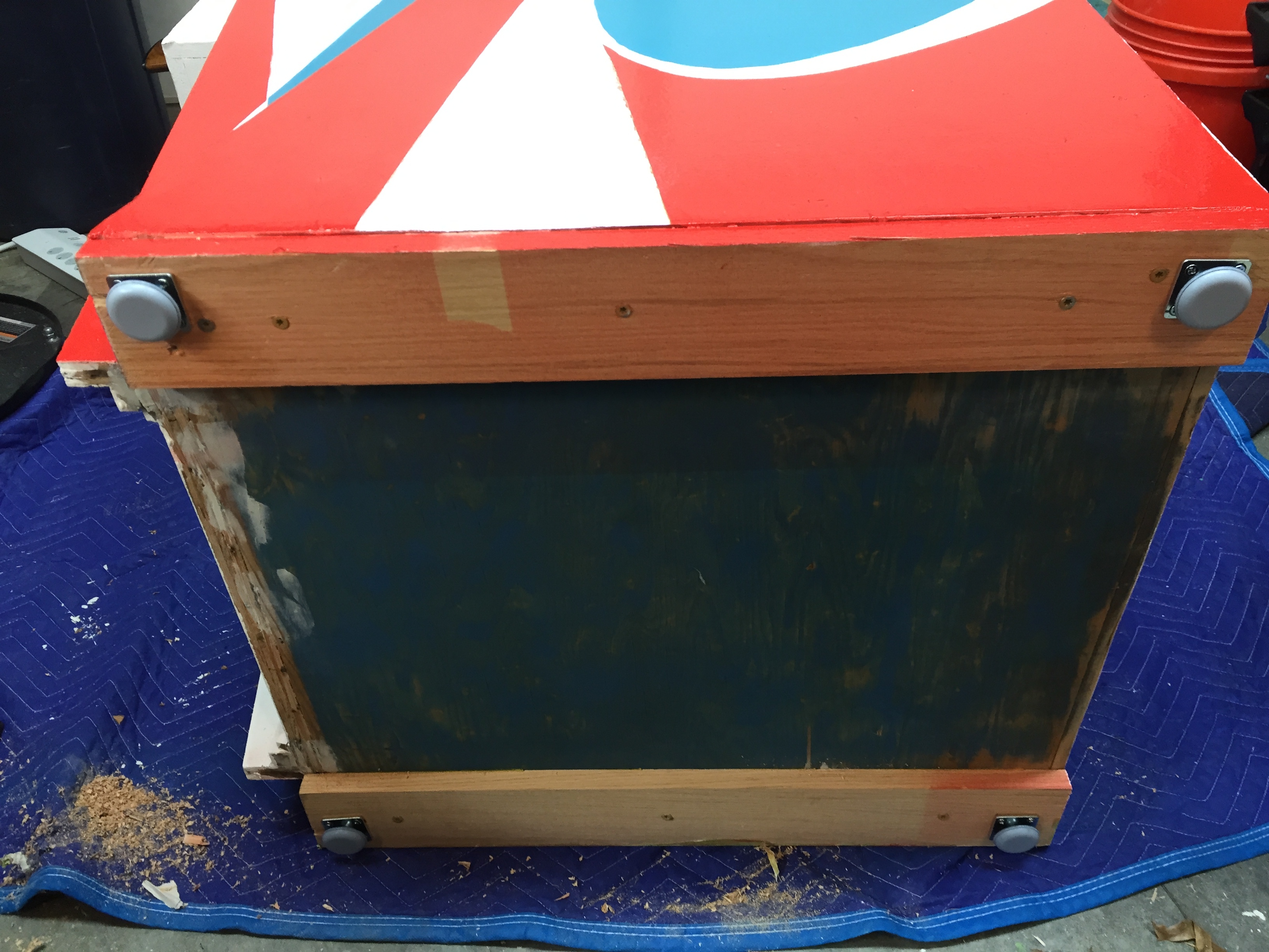
Leg Levellers / Adjustable Feet
I ordered new leg brackets and levelers for the game, as the old ones were completely rusted and bent. I got the nylon feet that are supposed to slide better. They do seem to work pretty good, although not quite as good as using good quality teflon sliders under metal feet. I would recommend them if you don’t want to bother with adding the teflon sliders. I ordered the brackets and feet from Marco.
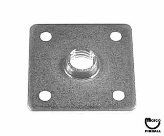
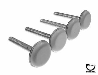
Here’s what they look like on the game:
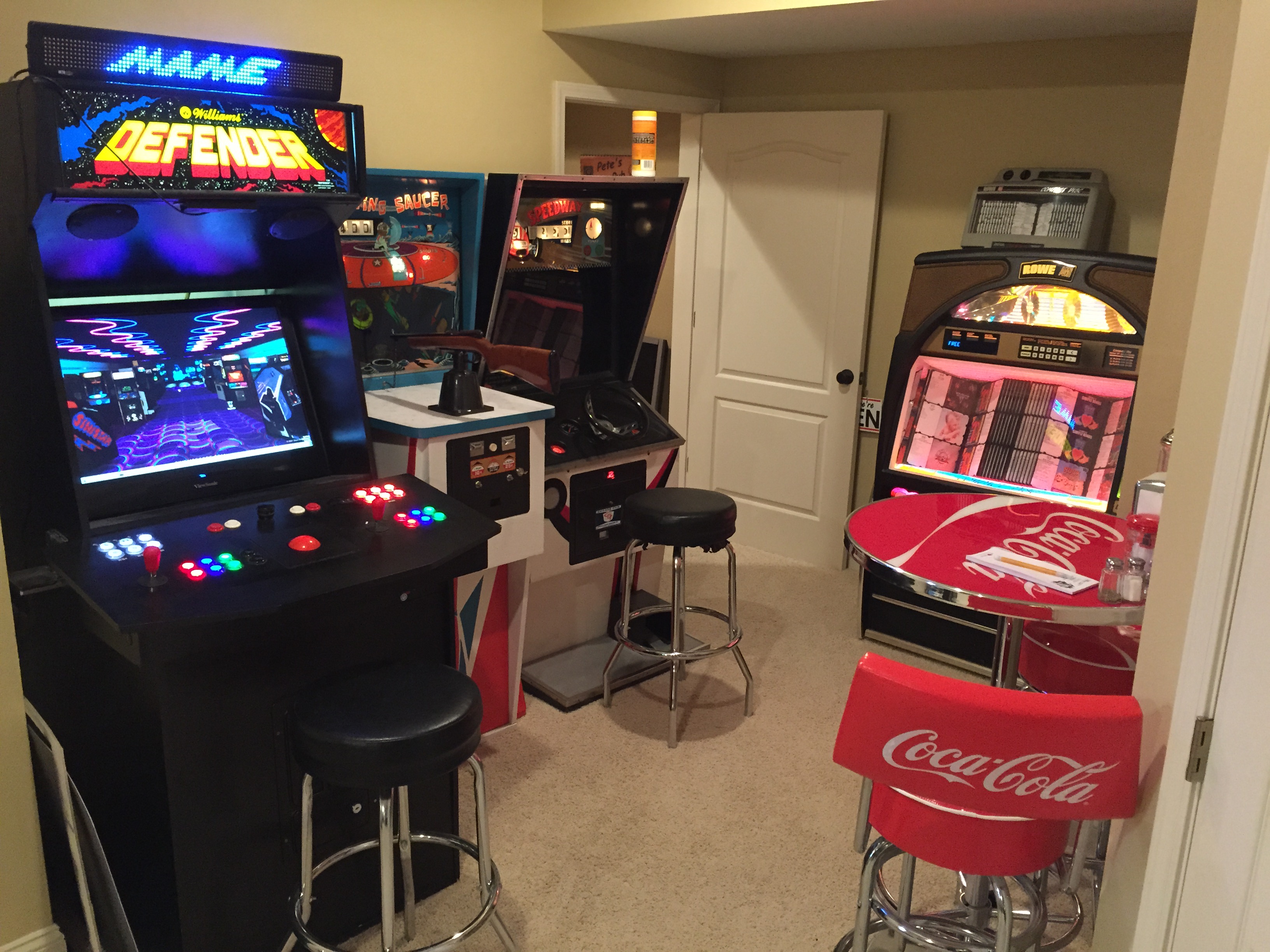
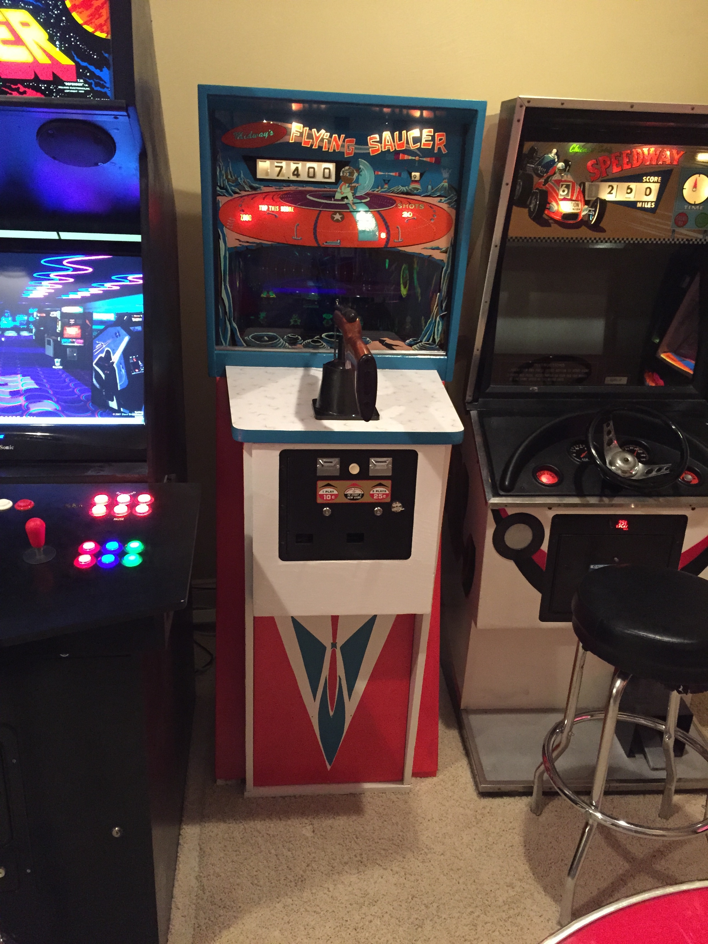
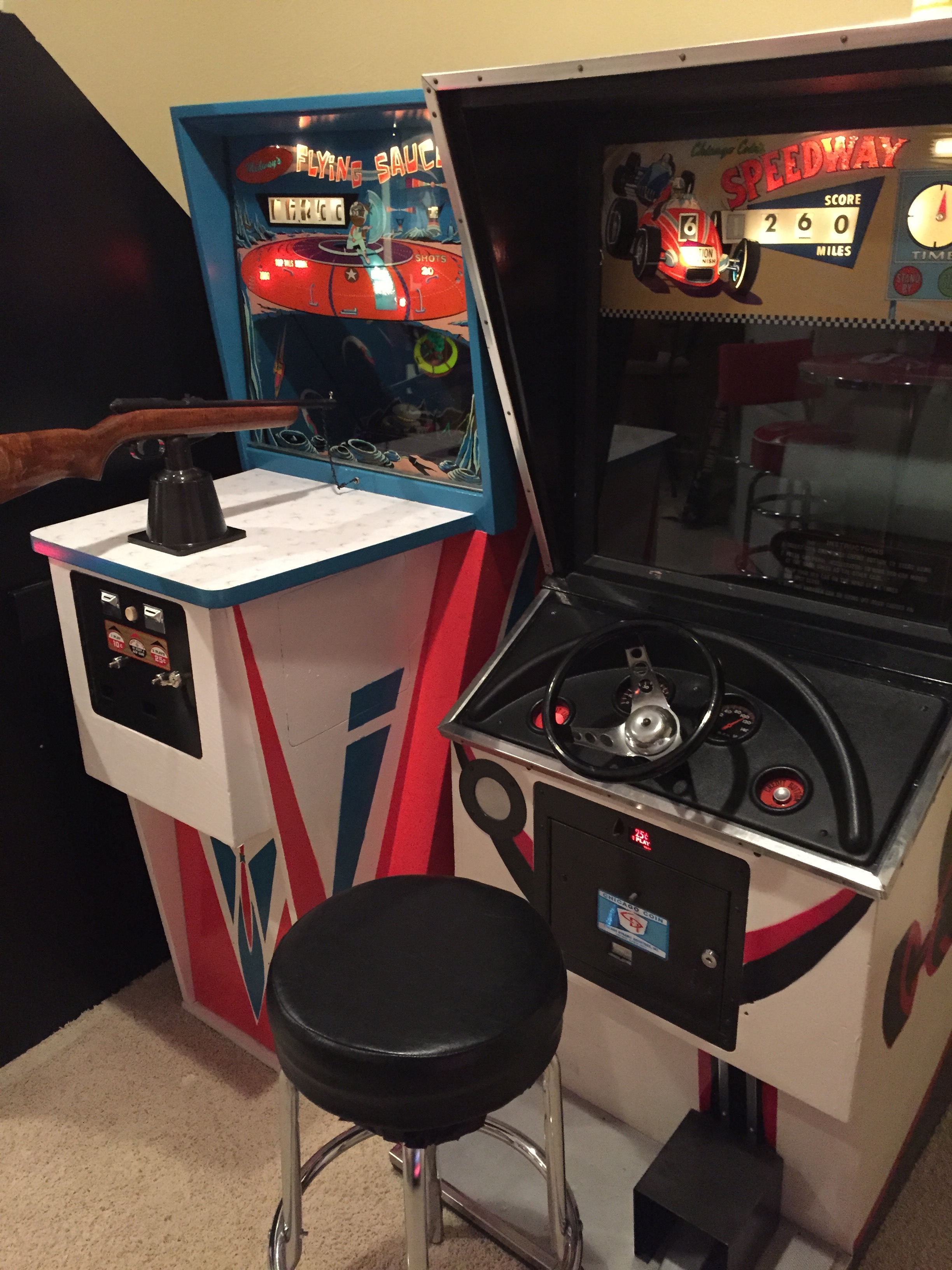
Moving the game into the Gameroom
I’ve got a few things coming for the game, but all my bit stuff is done, so I am ready to move it into the gameroom. I made some room between my Speedway driving game and my Mame cabinet for it.
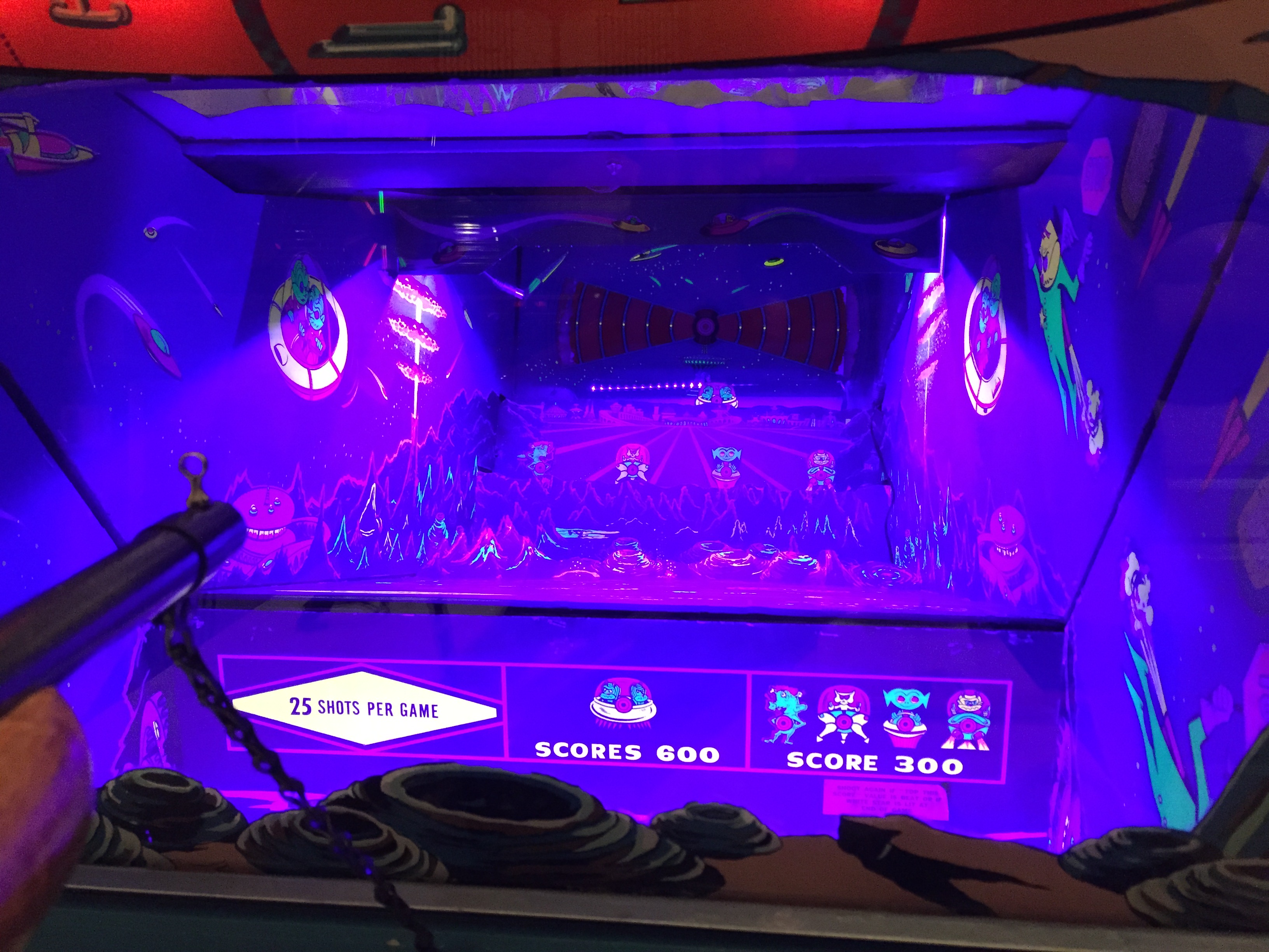
LED Blacklights – Not Recommended
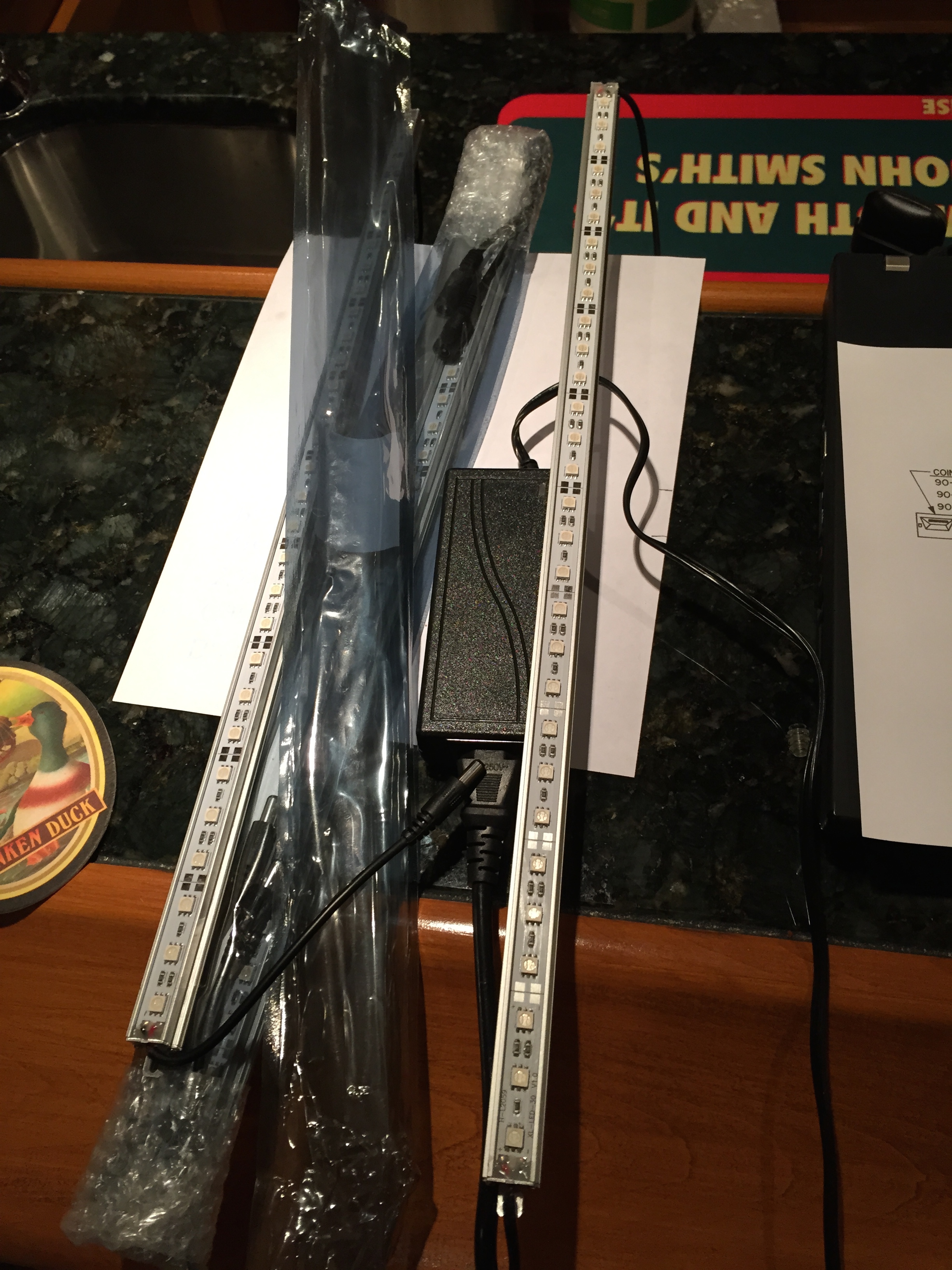
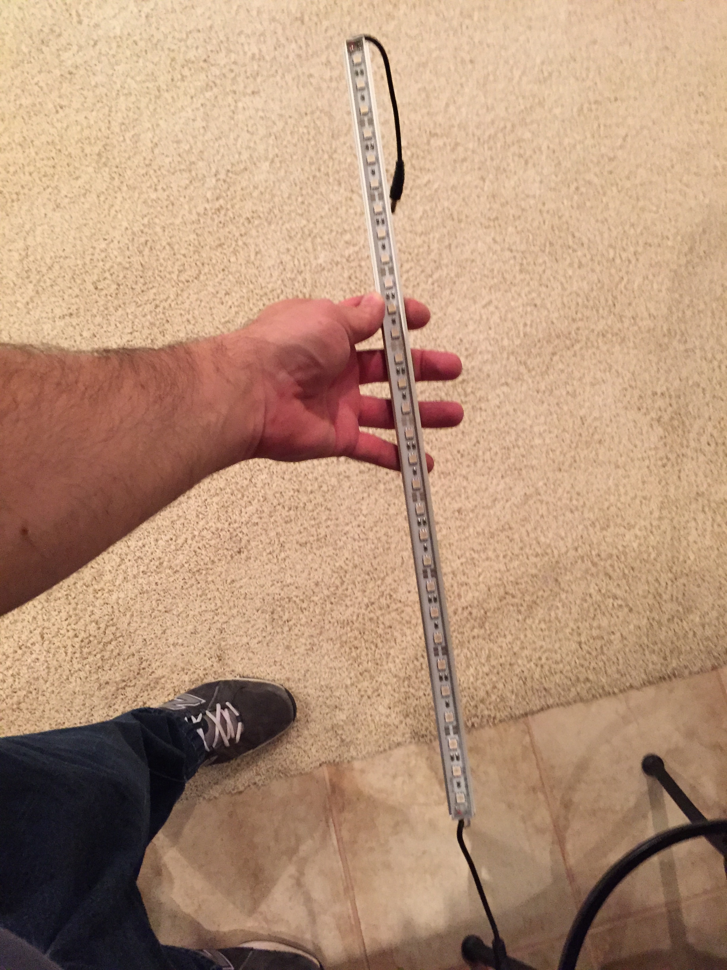
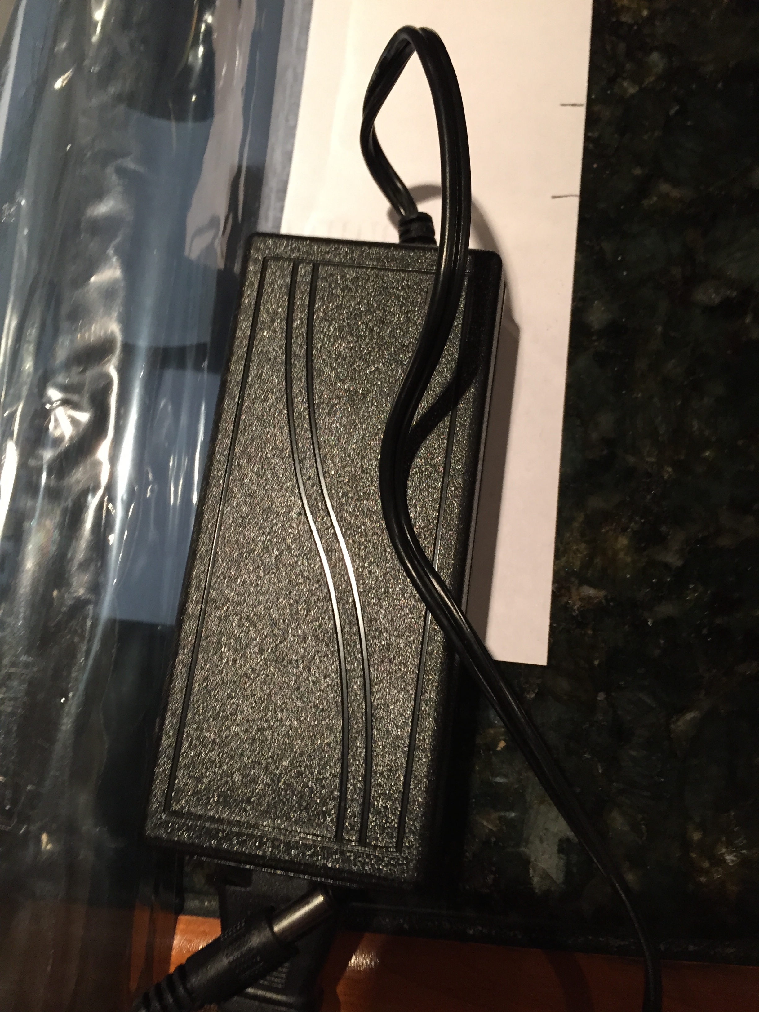
I ordered some LED black lights to add to the game to see if I could enhance the blacklighted graphics a little.
These things were very disappointing. They are not blacklights, nor are they UV. They are just purple leds. The units themselves seem to be decent quality – they are just not blacklights. Looks like I’ll have to find a different alternative.
Here’s what they look like and what they looked like in the game… I have to say, they are not recommended.
Gameplay Issue
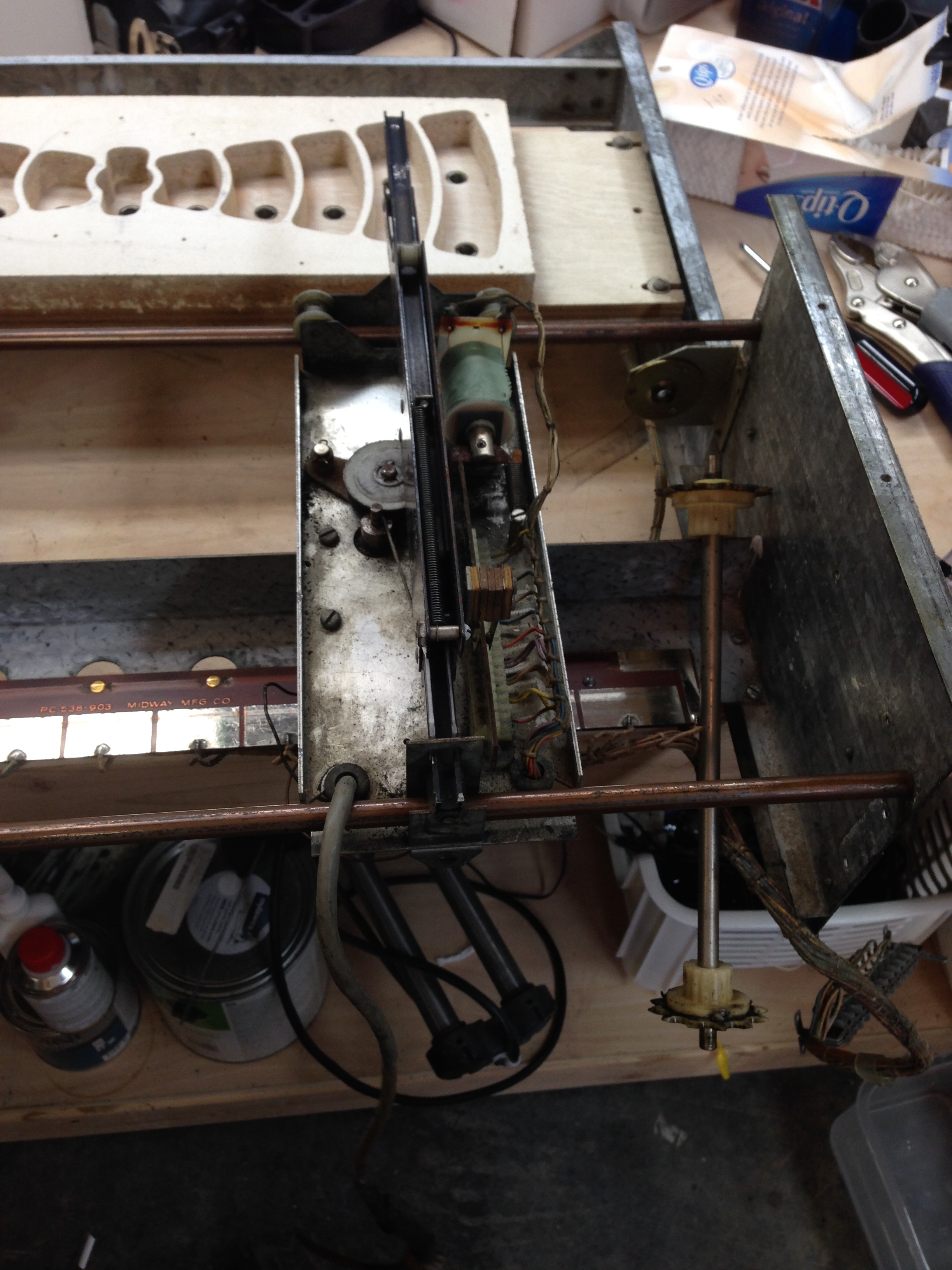
The flying saucer has been working, but I had suspected it wasn’t working as designed from the factory. The horizontal motion was working fine, but the vertical motion didn’t seem correct. The saucer would go up, and then go back and forth, but would not go back down again until it was hit by a shot, or when the flashing light target activated.
I always suspected the flying saucer should go up and down, back and forth, and sometimes “dance” a bit (quickly go back and forth and up and down is little bursts).
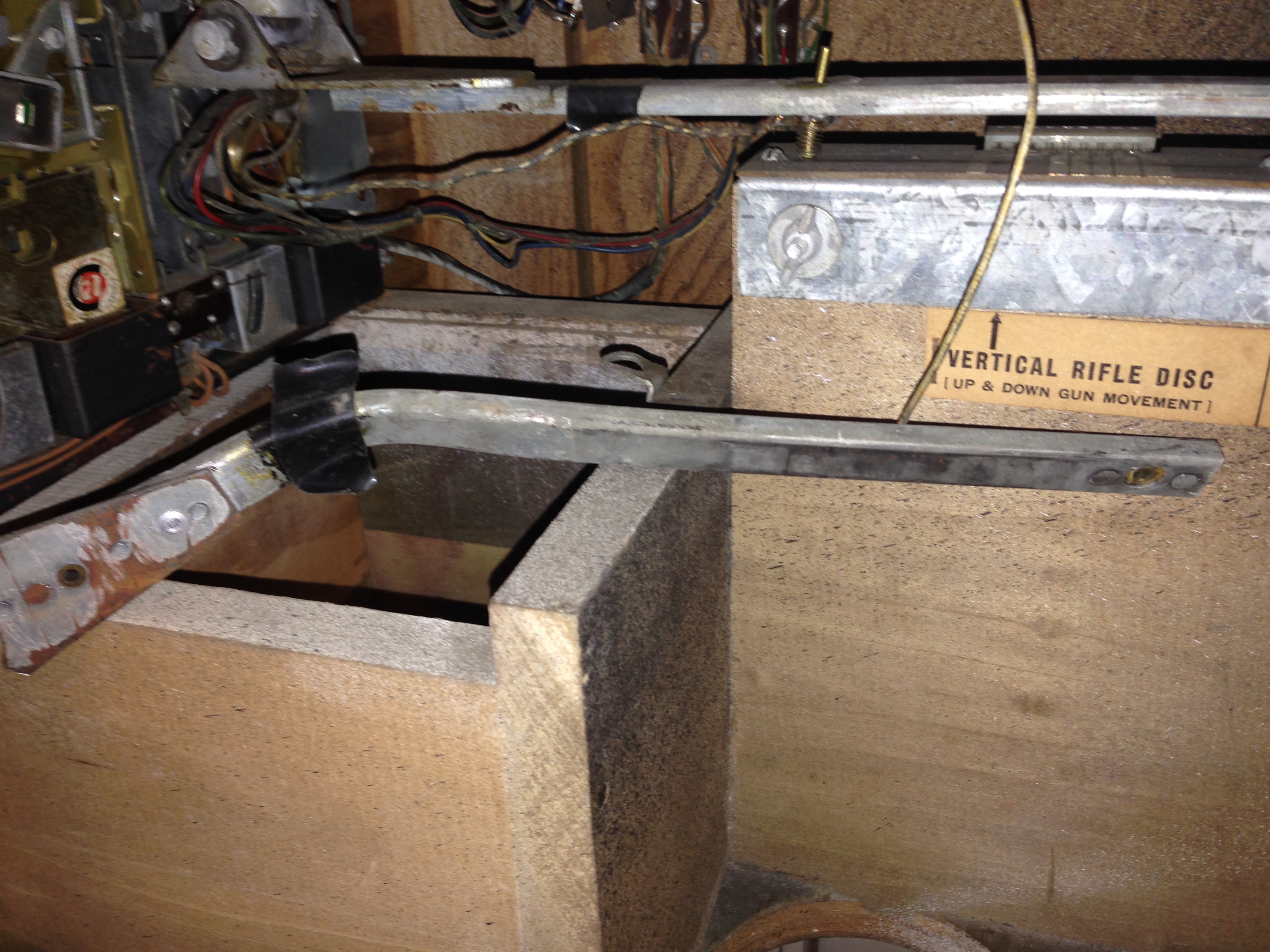
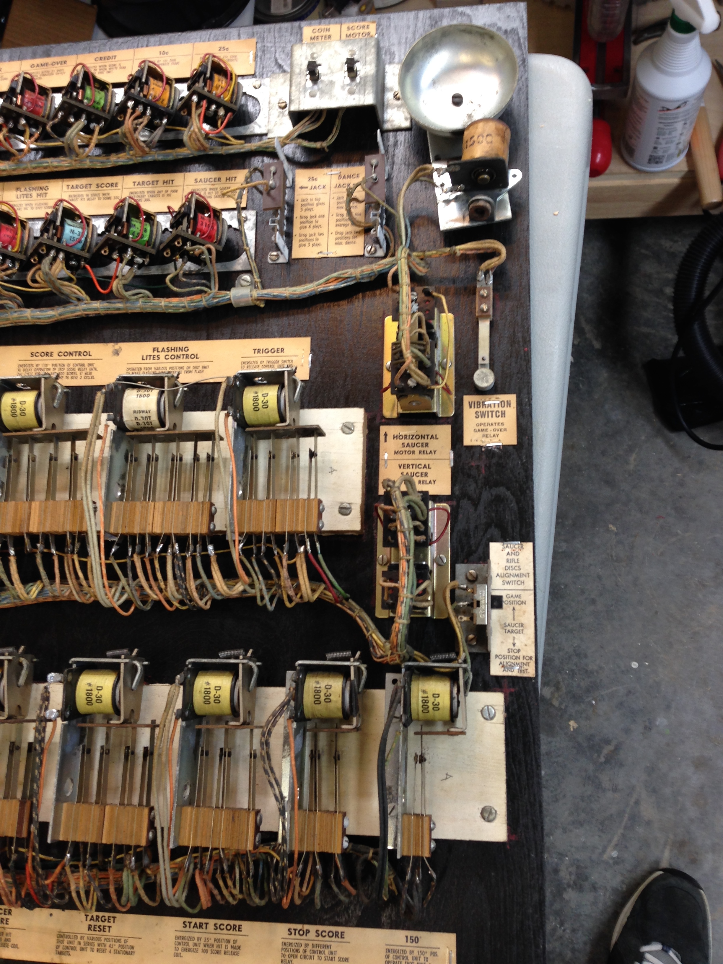
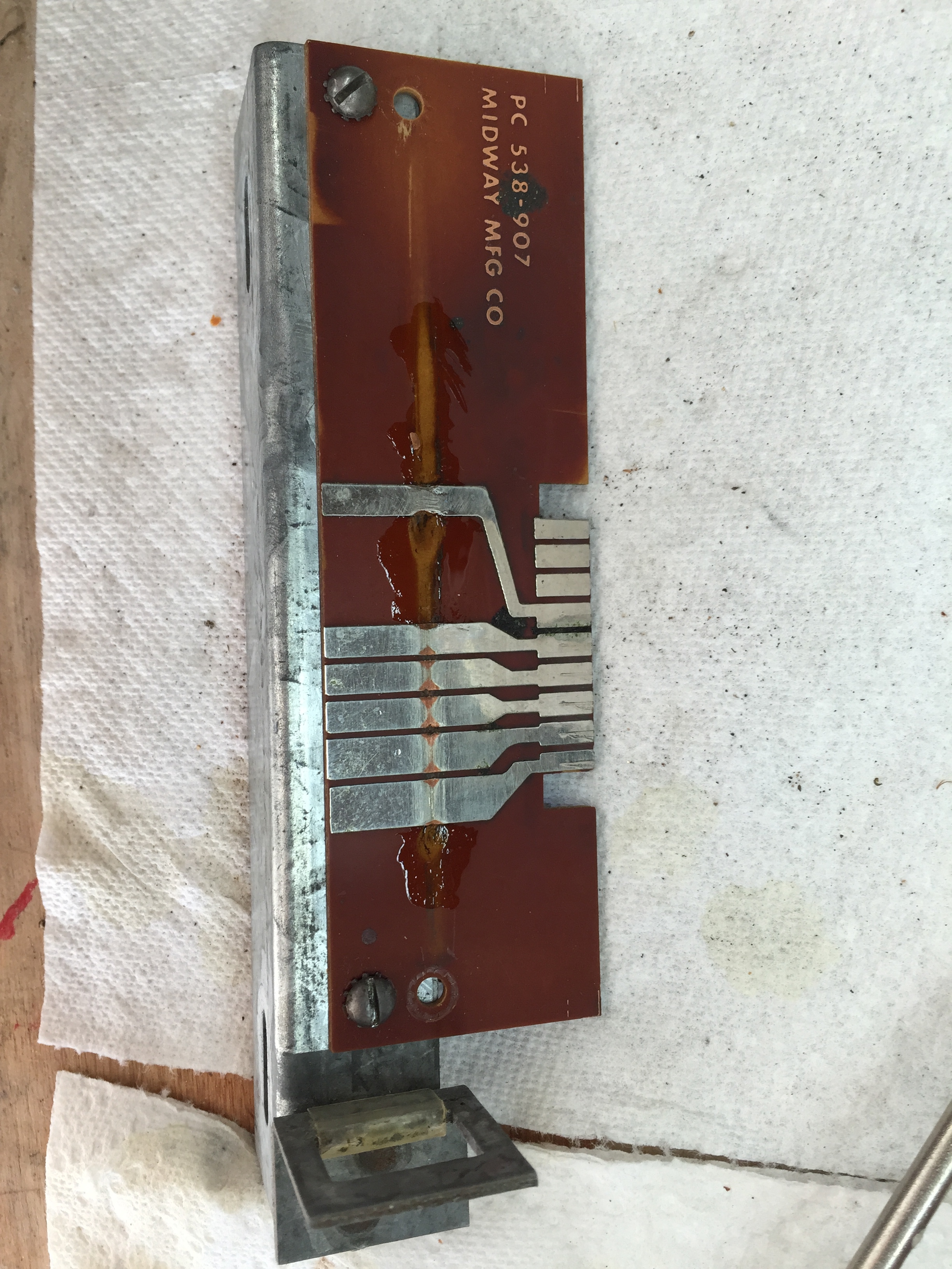
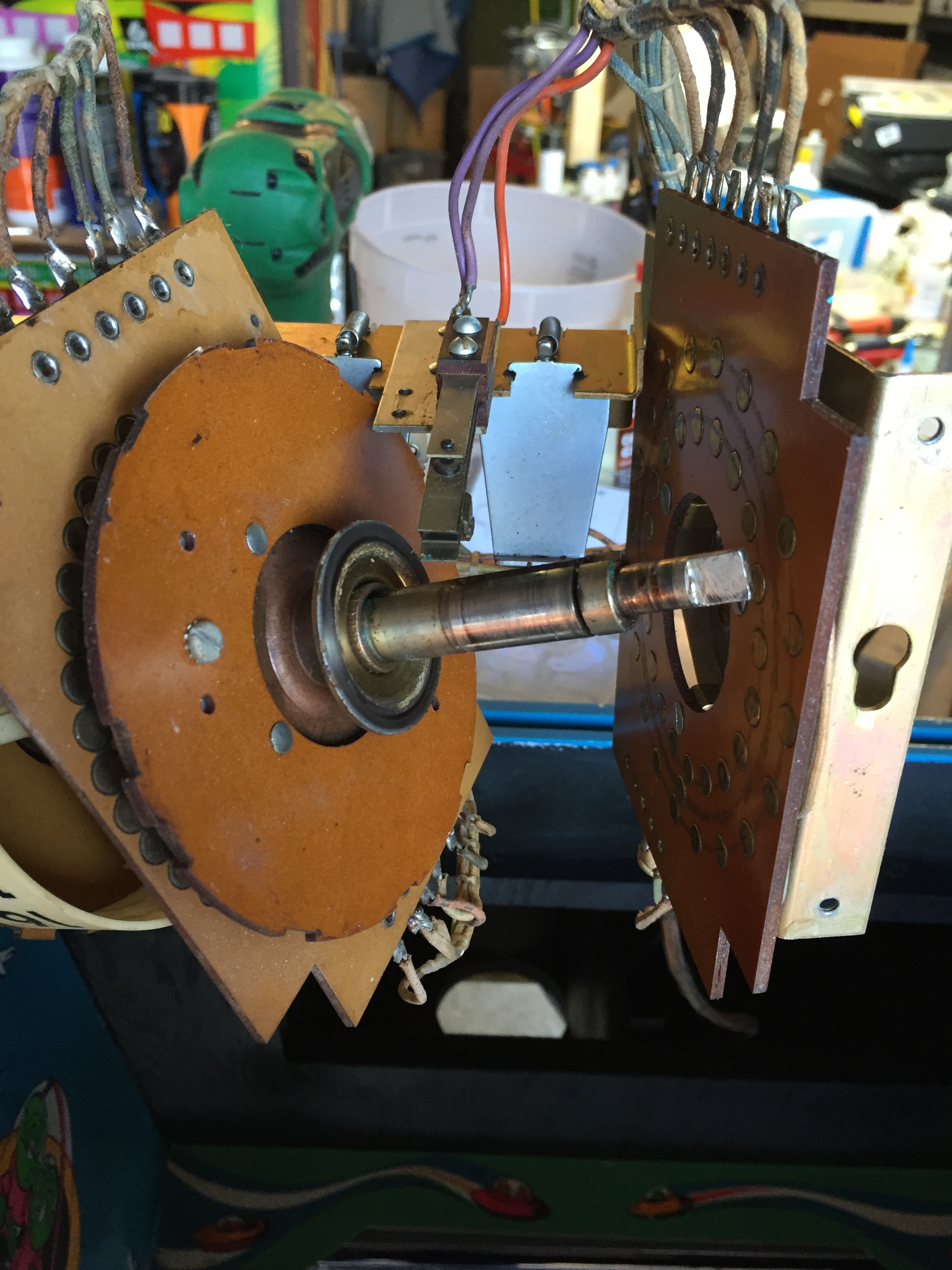
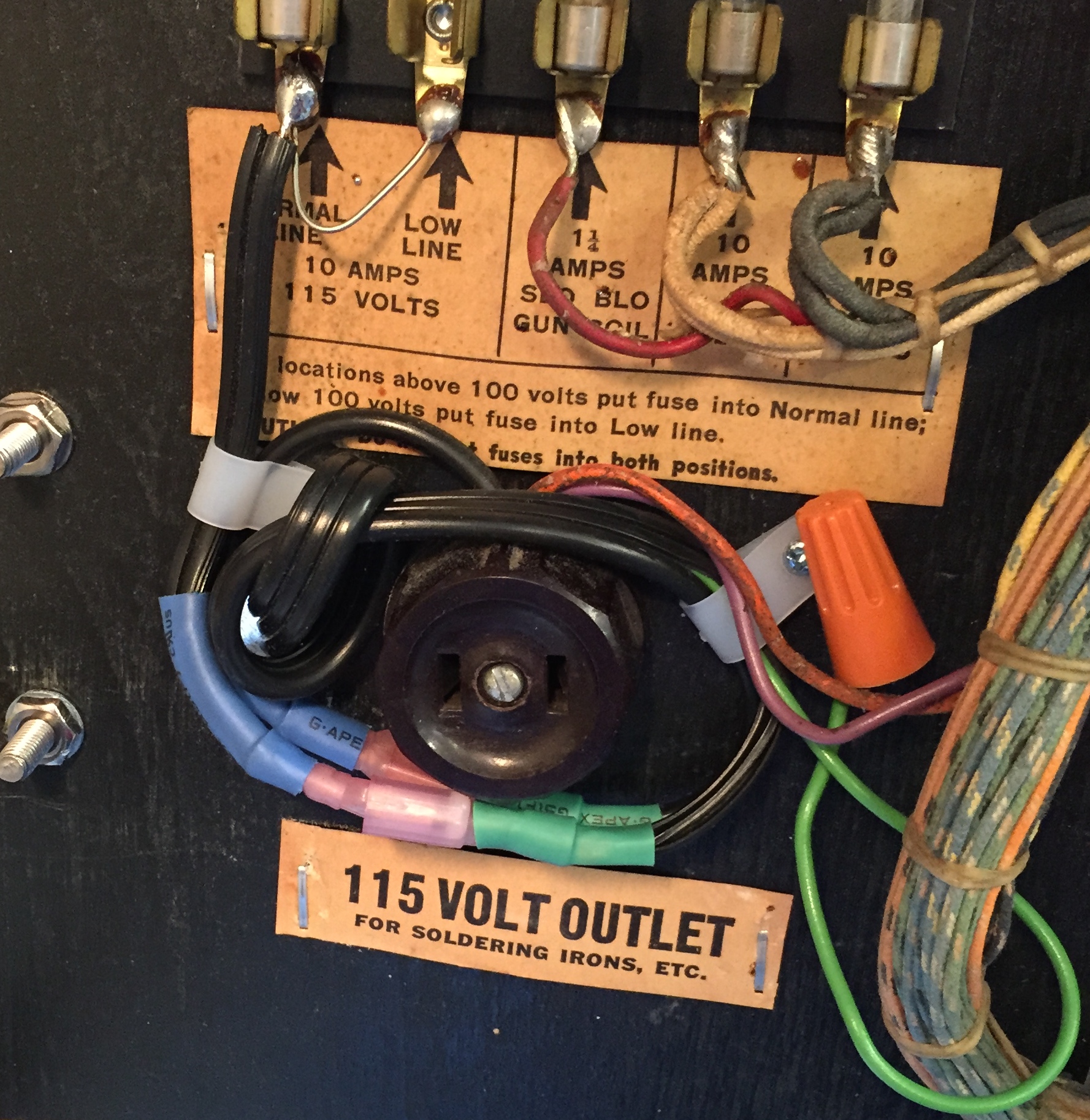
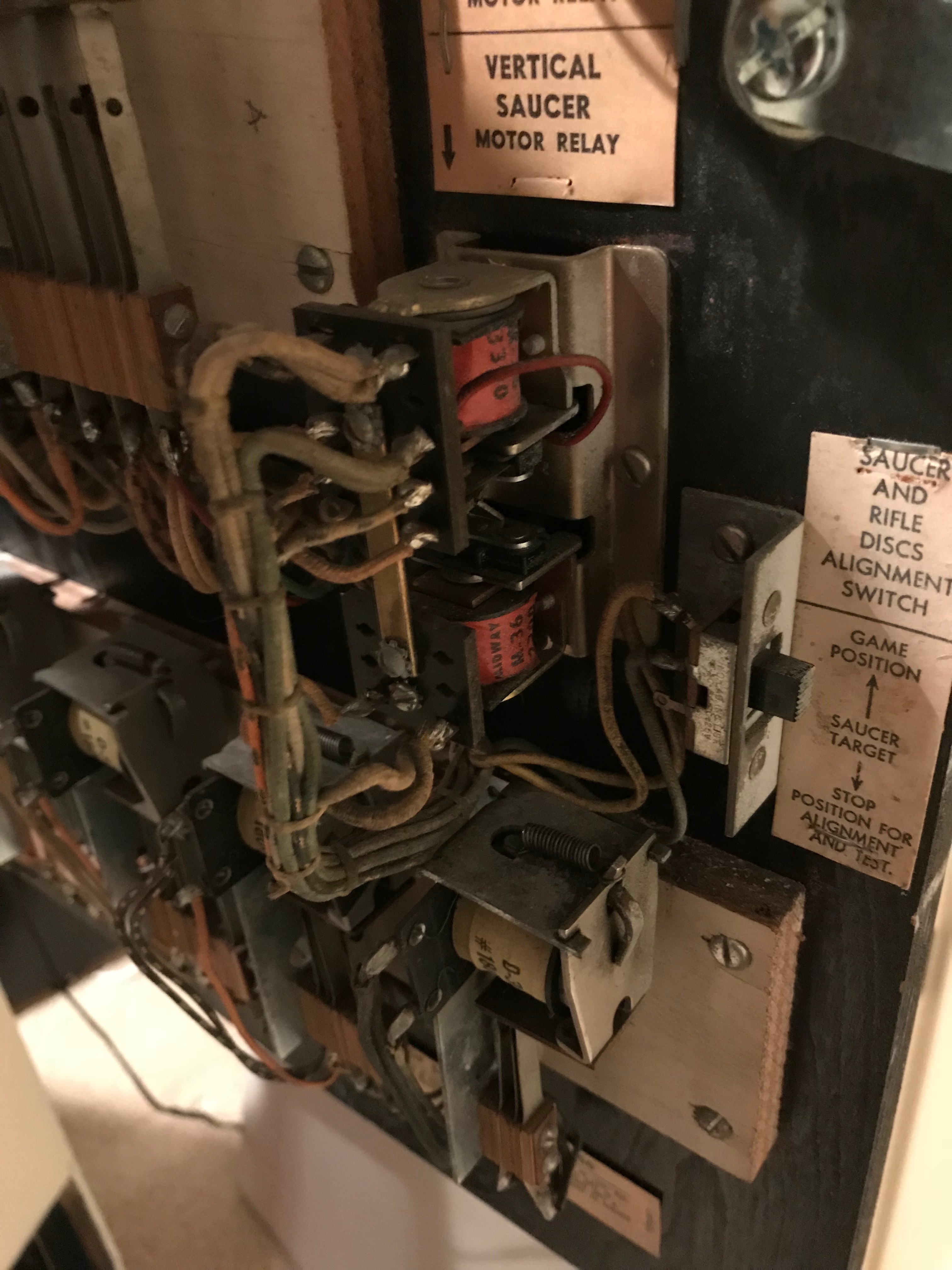 I dug into the schematic and looked at the relay that controls the up and down motion of the saucer, and also at the “vertical saucer disc”, which really isn’t a disc at all, it’s a bakelite card, with solder traces on it, that contacts on the saucer mechanism follow as the saucer goes up and down.
On one side of the card are the traces for the rifle position (tracks whether the gun is aimed at the target properly), and on the other side, it tracks whether the saucer is at the bottom or top of its travel.
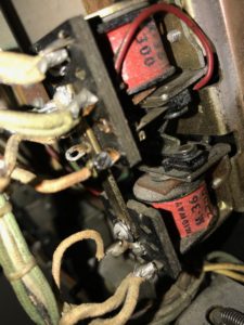
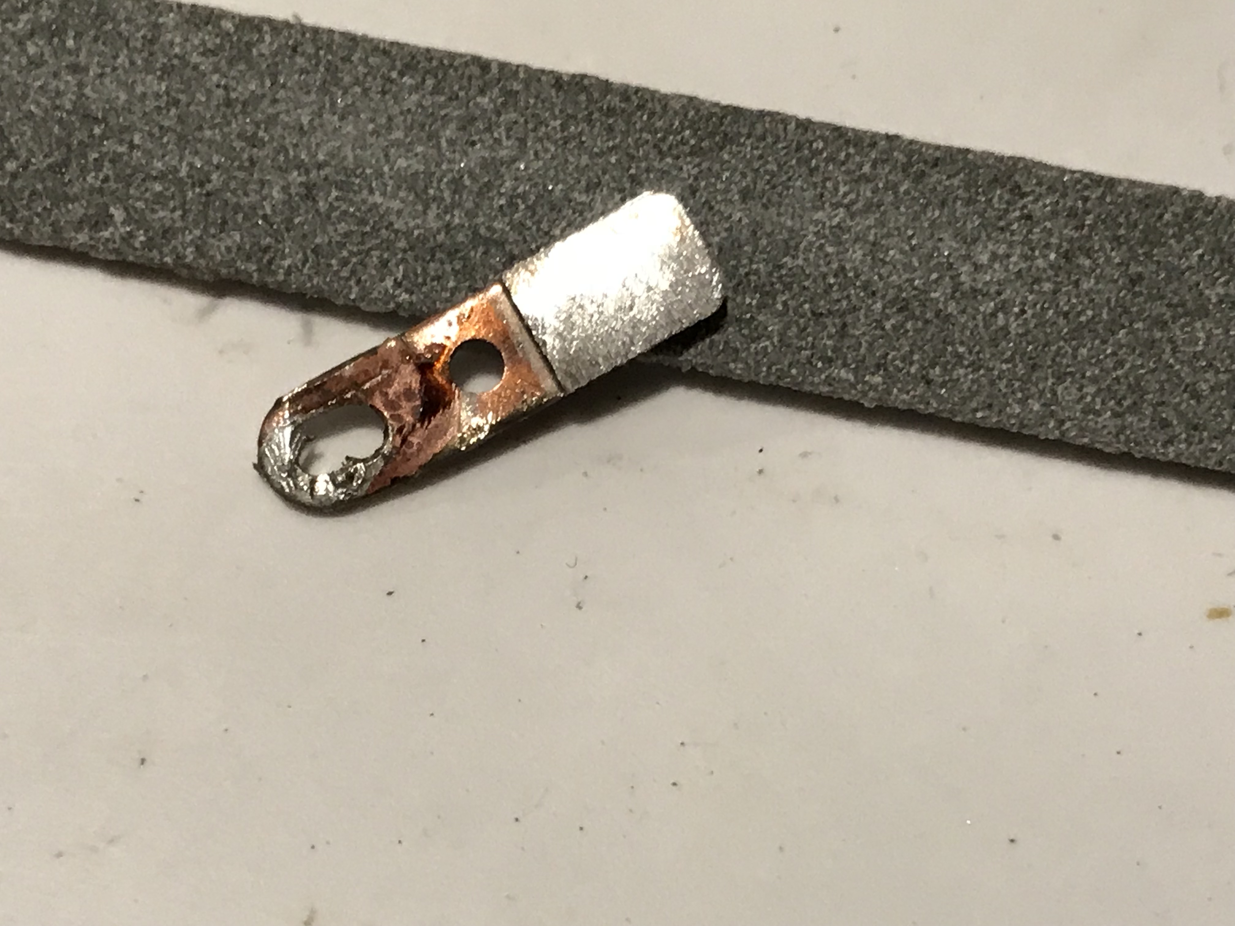
The contacts on the vertical saucer motor control relay were burnt and pitted from age and probably mis-adjustment. I tried filing them in the relay, but ended up having to remove them because it was just too much work to try to do this in the relay itself…
Pitted Contact (before aggressive filing)
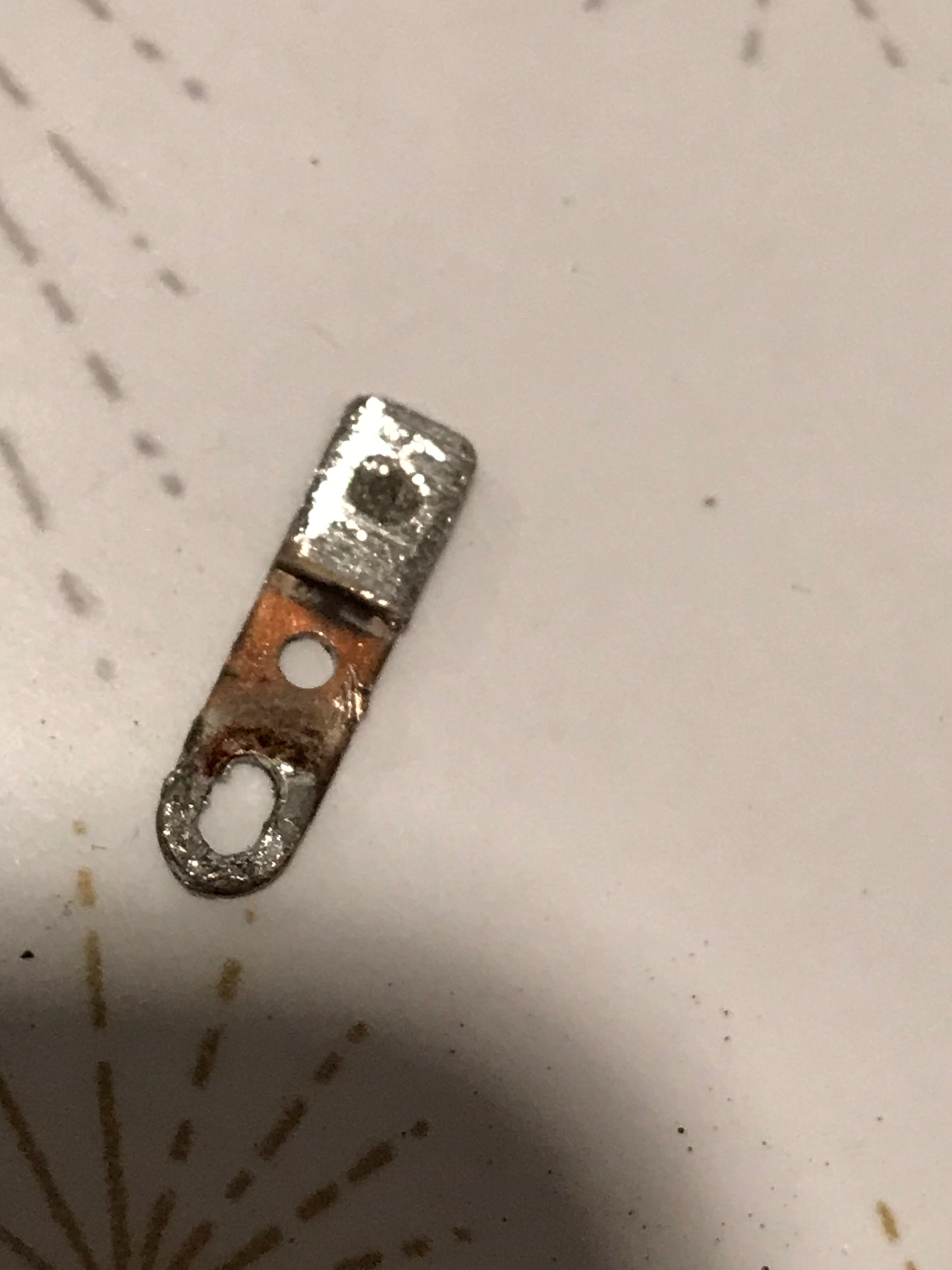
Filed Smooth (but not much meat left)
As I was looking at the mechanism and trying to figure out what was going on, I realized the saucer mechanism wasn’t able to travel to its maximum “up” position. After some disassembly and research, I realized that I hadn’t put this unit back together correctly. There are sliding gear tracks that have to be aligned precisely, otherwise the saucer won’t move up or down to its fullest amount.
After assembling the unit correctly, the saucer now moves up and down correctly and the game is a lot more fun!
Stuff Left To Do
1) I still need a 10 cent (dime) coin mech – very hard to find. There is a company that still makes them but as far as I can tell they don’t sell them directly (Coin Mechanisms Inc.), and I can’t find a distributor that carries them.
Update – I was able to find a 10 cent mech on ebay after some time. Now the coin door is pretty much complete.
I’m still wondering if the start button on mine is correct. Most pictures I’ve seen of other people’s games have a red plastic start button. Mine has a steel button which is unpainted, which looks original as far as I can tell.
I found part #90-009 on flippers.com which looks exactly like the button in my game.
Without a manual or parts catalog, I have no way to verify what the original button was.
2) Decide if I want BGResto.com to reproduce the backglass the target glass. So far, the paint loss hasn’t bothered me too much, especially since I’ve clear coated them and they won’t be losing any more. Still, the area where it says “Game Over” is in rough shape and I may eventually pull the trigger and send these off for reproduction.
Hi there – amazing restoration job – well done. i have a Skeet Shot game and I am trying to get new coils and at least one copper sleeve – any idea where I could acquire these from? I ma in Auckland New Zealand so any help would be appreciated.
Thanks
Hi Ian, thanks! There are a few places where I typically go for coils, coil sleeves, etc. My first choice is usually either Pinball Resource (http://pbresource.com) or Marco Specialties (http://www.marcospecialties.com/). For hard to find Midway stuff, sometimes Johns Jukes (http://www.flippers.com/) has the stuff you need. If you know the coil or part number, then it’s much easier. Do you have a parts catalog for this game? It would detail the part numbers of the parts in question. If not, you may be able to google the game and see if you can find a scan or pdf of the manual online. Is this the 1974 Chicago Coin Twin Skeet Shoot? If so, here’s a parts manual for sale on eBay for it right now (http://r.ebay.com/FtmjlB). I don’t know much about the parts market in New Zealand or Australia, but I’m guessing long distance shipping is going to be your only option.
Fantastic job. Thanks for taking the time to document your restoration. I just picked one up and everything is working but the recoil mechanism – I will have to try and track down parts for that. However, the previous owners didn’t like the original paint job and decided to try their own paint scheme. If you still have the stencils I would love to purchase them from you.
Hi Ryan, thanks so much for the kind words. It was a fun project, and we’re still enjoying playing the game. Well worth the effort to restore it.
My timing is horrible! I literally just threw away those stencils two weekends ago. I kept them for a while in case someone might want them, but I guess I should have kept them a little longer! Sorry about that.
Pinball Resource apparently still carries the coils for the recoil mechanism if it turns out that’s what you need. I’m curious where you found yours? I picked up mine off ebay from “coinopwarehouse”. I think I paid $550 for it. Probably a little much for a non-working game, but they are really hard to find.
Pete
I thought it would be a long shot on the stencils but figured it wouldn’t hurt to ask.
Thanks to the pictures I figured out that the half of the recoil mechanism that was missing was in the “extra parts” that came with the game. It was also nice to see the coil number to order as well.
I found mine from an old ad on craigslist and bought it just last week. I ended up paying $650.
I wasn’t even sure that I wanted to purchase it because of the lack of information on the game. I’m glad I did because its a fun game (the flying saucer is pretty hard to hit).
Awesome Restoration! Do you still have the game? Curious how much I would have to spend to get one of these for my basement. If you can even find one.
Hi Ryan,
Thanks for the kind words!!
I usually look for these in rough condition as they are more affordable that way. I sure don’t see too many come up for sale/auction in restored condition, but guessing between $2k-$3k. I think I paid roughly $700 for this one. Try a search for completed items on ebay, and search for something like “arcade gun game”. I found a few that have sold recently.
Pete
Thank you Peter for the fast reply, it was up for auction just last night and was really hoping to get it and start this journey with my first EM game. I was ready to spend 1000. Sadly I wasn’t ready to spend what it went for as my first attempt at restoration. Final price was 1600 plus tax and the auction fee, ~2000. Now that is a nice comp for your machine.
I’m not sure if your still looking for the 10 cent coin mechanism but St. Louis ball bowlers sells one that might work.
Hi Ryan,
I’ve been wondering if my flying saucer is moving around correctly. It moves back and forth, and slowly moves up, but once it’s fully up, it doesn’t move down at all until it’s hit. Would you mind posting a video of your saucer in action so I can see if mine is working the same way please?
Pete
Hi Pete, great restoration and excellent step by step how to detail, thanks for that. I just found one on Craigslist and hope to start restoring it in a few months. Your ideas will help tremendously.
Hi Joe, I’m so glad it will be helpful !
Good luck with your restoration. Post some pictures please, would love to see before and after.
Pete
My game is missing the lower front removable panel. Any chance you can give me some info on yours such as height, width and thickness? Is it plywood? Does it just slip up into place then drop down into the bottom groove similar to how a backglass does?
Oh wow, my memory is terrible. I can’t remember for sure. I believe it is plywood, and I think you are right, it slips into place, and maybe has like two screws at the top that hold it in place. I’ll be home next week and will pull it out and measure and send you some better pictures. I believe it is probably 1/2″ plywood.
Great article, I scanned it but need to go back through it. Just picked one up, works mostly I think. My first EM gun game, I have 15+ EM pinballs in storage that I plan to get to soon. Basically, no EM experience. Do you happen to have a scan of the manual or schematics? Thanks, Bob
Hey Bob, thanks for the kind words. I was never able to find a manual or schematics for this machine. I searched and searched but it almost seemed like they never produced a manual for it – seems odd, but I can find no evidence of its existence. I have a manual and parts list for “Twin Pirates” which is similar and might be helpful. I’ll post them to the page. Please let me know if you happen to find anything on this machine – would be great to have the real manual and schematics. It’s a really fun game.
Hey Pete, first let me say you did a great job on your Saucer project,I was wondering if you have anymore pics of the saucer vertical wiring cable? I have one that someone hacked all the wiring from the plug to the vertical board . I bought a schematic but it don’t show a good description of it .Thanks Ron
Sure, I’d be happy to. Which harness are you referring to? Maybe send me a picture of the area you’d like me to focus on. I’ll shoot you a private message.
Hey Pete, are you able to share the 1970 Parts catalog? My email is kevinjbradley@gmail.com. Thanks!
Sure, I’ll have to scan it in though. Is there a particular game you want, or just the whole thing?
I actually just need white lightning. Any other generic stuff like relays or cray units would also be good. Thank you!
Ok, I’ll dig the catalog out and either scan it or photo those pages for you.
Pete
Hi Kevin, I have to humbly apologize I totally forgot to post these photos.. I’m just posting now, what a cool game, I hope you get it up and running – it looks like a lot of fun! I’m going to create a post called “White Lightning Photos”. Here’s a link https://www.petesgameroom.net/white-lightning-photos/
Thank you for the information on this page. I was finally able to, properly, reassemble the moving target assembly and get it back in the machine and possibly working… I’m missing the drive ring (part # 542-902) so still trying to get that… and I have to figure out where a broken wire on the connector that the PCB (PC 538-904) plugs into… ANYWHO, I had to reproduce that PCB (538-904) as mine was broken, only needed 1 but had to get 3 made. I’d really like to send you one as thanks so you’d have a spare just in case… although mine is shaped differently than your’s.
I think you’d have my email from this form, so if you’re interested just email me and let me know and I’ll get it in the mail to you.
Hi, sorry for the slow reply, I was having issues with by blog not emailing updates. That’s awesome that you had those cards remade. I think I do have your email address when we traded some emails – I’ll have a look. It would be nice to have a spare.
Hows the game coming – is it getting to the point where you’re able to try it out?
Peter
I have just found and bought a Flying Saucer game. I have a question on the dancing saucer mechanism. The cord that pulls the saucer up is gone, so how long is that cord and does it wind around the drive wheel when it is down or just long enough reach the wheel. Any info would be great.
Mark
Hi Mark, sorry for the slow reply – I had an issue with my blog not notifying of new comments.
Anyway, I believe what I did was to take a longer piece of nylon cord, and I attached it to the pully, and then moved the mechanism all the way extended upwards, and then I ran the cord through the tie-point and tied it off – taught.
Thanks peter, that makes sense to me. I will let you know how that works. I still have a lot of things to do.
Mark
Hello, I’m wondering if you can help me with some restoration questions. I am uncertain as to where two wires go that have come off of the area around the vertical saucer motor. These two wires have come off and the schematics are not helpful. Thanks!
Hi Greg, sorry for the slow reply, I still seem to be having email update issues… From your picture I can’t really identify those wires, or where they are coming from. If you’d post some additional photos of the area, showing the wire bundle, and the mechanisms in the area where those wires may reach, I can try to compare to my machine.
Pete
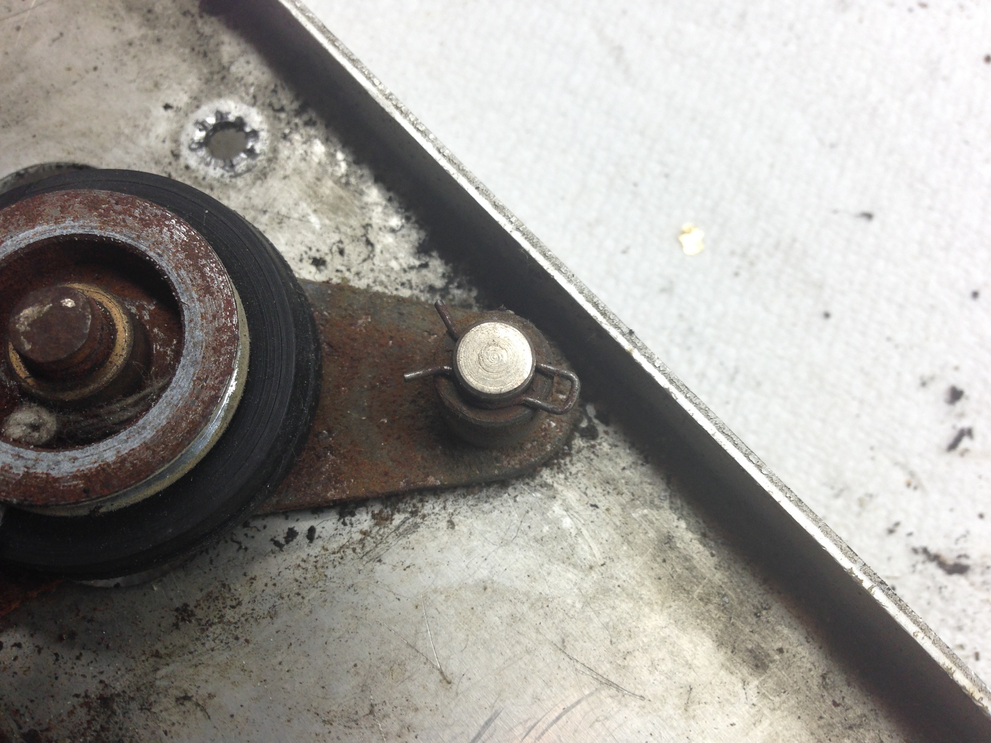
Hey Peter….Great Job, Thank you for all this info. Just picked up a Flying Saucer for $750. Seems to work with some minor issues. Were you ever able to locate a Manual? I do notice the latch and spring are missing on the credit coil…looks like I’ll have to reconstruct one of these. I have an original Schematic of the wiring that I’m going to try and copy tomorrow on our Blueprint Copier at work. Hopefully the creases won’t show up in the copy.
If it turns out OK ….I can mail some out if anyone needs it.
Hi Jack, thanks for the kind words. No, I never found the manual but I posted one that was close, similar parts. The schematic would be great, I can attach it to the page if you like. I’m sure it would come in very helpful to others.
I am working on restoring my flying saucer. The upper contact board which the stylus rides on that came with the game doesn’t seem to be the correct one. Could you take a picture of that board for me to compare it to?
Hi Russ, I don’t have the game at my house at the moment, so might take me a bit. Are you looking for a picture of the solder traces on the board?
Pete
I found this in my photos, maybe this helps?
Lucky me I am just heading out to pickup a flying saucer barn find and came across your page. great info for restoring mine.
Looks like you have a great machine to start with. Yours is the first I’ve seen with the 10 cent and 25 cent sticker like mine. Hopefully yours will be complete inside and in good shape. Good luck!
weird I posted a couple days ago and my post is gone
So glad that I found your site and the extensive work you’ve done on Flying Saucer. I bought mine this week and have started to plan what I need to fix myself and what parts I need to purchase (like feet). You do excellent work and help motivate many of us out here to take on home repair. Attached is the acquisition. 64834 on the game counter..
Thanks so much for the kind words! Your machine looks to be in really good shape. Hopefully it won’t need much more than cleaning up old dried out grease and re-lubricating. 64000 quarters! That machine probably made someone 16,000 bucks. Not a bad return.
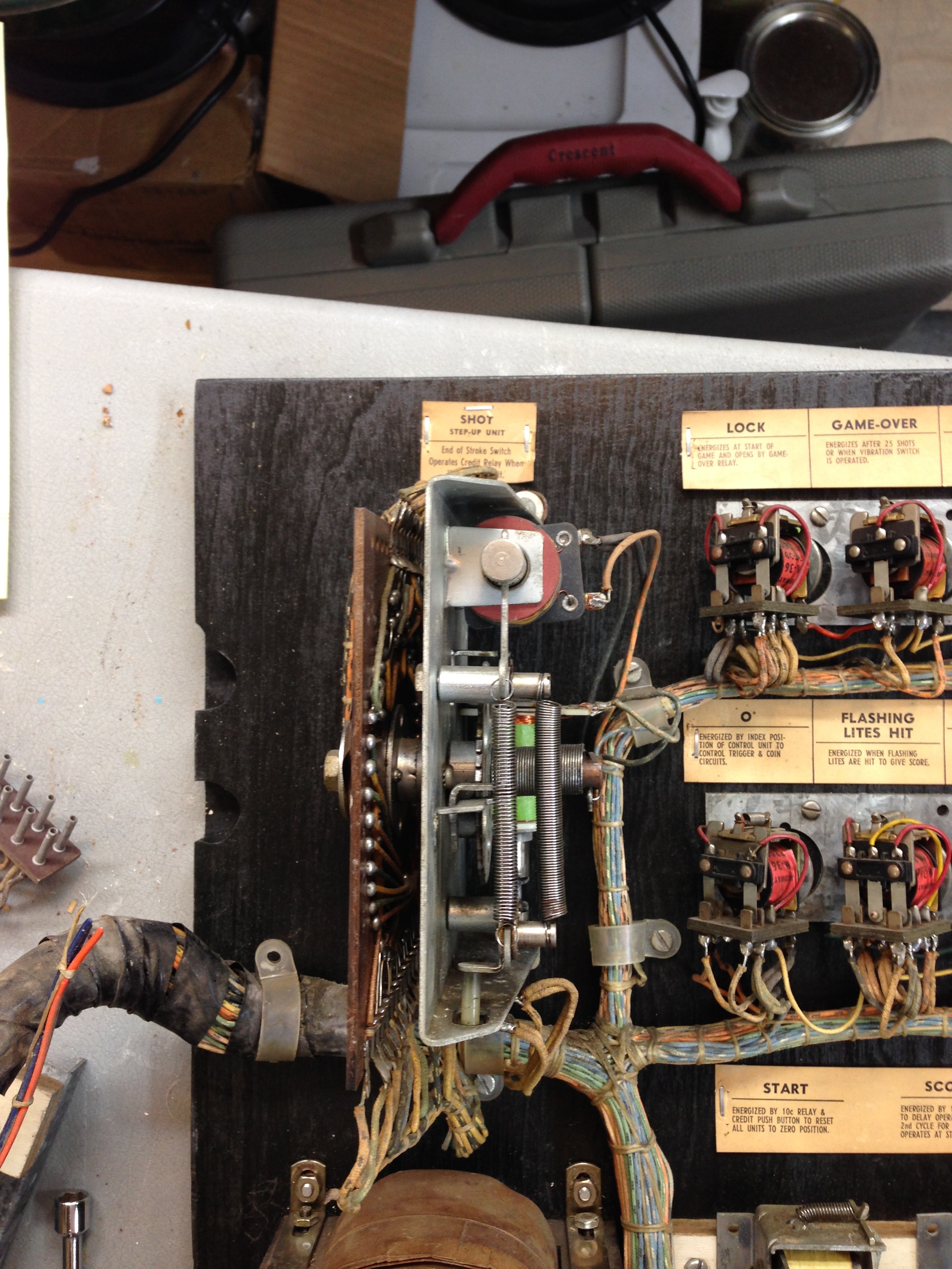
I need to get a picture of the upper wiring for the control unit. Do you still have this, can you post a high res picture so I can see the wire colors please?
Hi, sorry the machine is at a friends house, will probably be a while before I could get a picture.